• The move to the new server is done. There are some software and database maintenance updates in process. This has us passing the hat around to help out. We appreciate any donations. Seriously, even a dollar helps. The payment page may be found here - https://www.audiokarma.org/support.html

Pioneer M-90 Issue- need help.

some circuit and chip variances will make things less than perfect (hence +/- 5% or 10% is a tolerable tolerance). resistance measurements on the chip pins helps with looking for unusually low resistances (shorted internally or low resistance) and considered to be a crude/low-level component test (still useful though). in terms of overall chip functionality, only in a circuit with power applied and design spec load connected will it show if it works or not (multi-pin mystery box).


are the numbers with or without dim bulb and is there a load connected?

the numbers in post-119 are the original outputs (power transistors)?
The numbers are "without" the DBT and "with" all the original transistors. I've not put a load on the speaker terminals yet.
 
Last edited:
some circuit and chip variances will make things less than perfect (hence +/- 5% or 10% is a tolerable tolerance). resistance measurements on the chip pins helps with looking for unusually low resistances (shorted internally or low resistance) and considered to be a crude/low-level component test (still useful though). in terms of overall chip functionality, only in a circuit with power applied and design spec load connected will it show if it works or not (multi-pin mystery box).


are the numbers with or without dim bulb and is there a load connected?

the numbers in post-119 are the original outputs (power transistors)?
I put 8 ohm resistors on the speaker terminals. No DB tester and no signal running thru the amp. DC voltages on pins 8 and 14 were slightly higher and pins 10, 11, and 12 were about the same for both channels. Reading DC voltage across the output resistors: -.02mV on the left and +3mV on the right.
 
some circuit and chip variances will make things less than perfect (hence +/- 5% or 10% is a tolerable tolerance). resistance measurements on the chip pins helps with looking for unusually low resistances (shorted internally or low resistance) and considered to be a crude/low-level component test (still useful though). in terms of overall chip functionality, only in a circuit with power applied and design spec load connected will it show if it works or not (multi-pin mystery box).


are the numbers with or without dim bulb and is there a load connected?

the numbers in post-119 are the original outputs (power transistors)?
Took a look at the overload detectors- Q127 L Ch and Q128 R Ch. L Ch E= -.3mV, C=11.4V, B=24.8mV; R Ch E=4.4mV, C=11.73V, B=30.1mV. Also fired it up on some speakers and it's sounding pretty good. L Ch heat sink running at 105 degrees (F) and right at 106 degrees
 
sounds like things are reasonably balanced, nothing going into high stress mode nor pulling too much power at idle.

i am guessing that the rear panel impedance switch is staying at 8r for most of the tests and measurements up to now?

not sure if i have gone down the LCR meter rabbit hole in regards to chip resistance measurements (at either 100hz or 1khz). probably best not to rock the boat when things are stable.
 
sounds like things are reasonably balanced, nothing going into high stress mode nor pulling too much power at idle.

i am guessing that the rear panel impedance switch is staying at 8r for most of the tests and measurements up to now?

not sure if i have gone down the LCR meter rabbit hole in regards to chip resistance measurements (at either 100hz or 1khz). probably best not to rock the boat when things are stable.
The overload detectors are 2SC1845s. I have some KSC1845s- do you think it's worth swapping those to check and see if it makes a deference on the numbers or are the differences not enough to worry about? I know the reading on pin 11 of each chip, which appears to be roughly the same as the DC offset for each channel, is not caused by the chips since that reading didn't change when I swapped them in post 119. Also, considering trying the replacement power transistors again now that I know they were not the cause of the protection issue earlier. Don't expect them to clear up anything, but for longevity they still might be a good idea. Thoughts?
 
The overload detectors are 2SC1845s. I have some KSC1845s- do you think it's worth swapping those to check and see if it makes a deference on the numbers or are the differences not enough to worry about?
should be fine, the newer components and slight variance in hfe or other electrical parameters might help as well (less np or pn junction leakage). the ksc1845 is a drop-in replacement for 2sc1845.

there are some sites with substitution lists, ak has more than a few versions plus other random sources.


Also, considering trying the replacement power transistors again now that I know they were not the cause of the protection issue earlier.
now that more variables have been identified that were influencing the circuit things should be stable now. the new outputs should have no issue handling 4r/8r loads and do so much easier. final listening tests will be need though to critique the new outputs and their dynamics, +/- sonic flavor.
 
Put the new power transistors back in (2SC5200/2SA1943)- no other transistors were swapped. Didn't want to change multiple things at one time. Full up and running there's no notable change at all in the 119 post readings. Running at the same temps and I'd have to say there's no notable change in sound quality- good or bad. I'm happy those are working! Trying to decide if it's worth changing the overload detectors. Would like to swap out the pre-drivers, at least Q123-126 since the run at over 100 degrees F with a heat sink. Thinking they could use a refresh but have to wonder if the replacements are legit. Does that lower line of transistors look legit to you? Originals are above and are currently installed.
 

Attachments

  • FR2.jpg
    FR2.jpg
    64.2 KB · Views: 19
  • IMG_20260520_175129986.jpg
    IMG_20260520_175129986.jpg
    126.3 KB · Views: 19
Screenshot 2026-06-11 at 19-08-58 2N3055 - 2SC2238B.pdf.png

the "new" 2sc2238b has an "o" suffix, not sure if it would be an issue assuming the new components are 100% up to spec vs fakes.

a drop in replacement for 2238 and 968 would be:


and can be sourced fresh from mouser or digikey or other reputable primaries.

Does that lower line of transistors look legit to you? Originals are above and are currently installed.
difficult to critique a 2d image of a 3d object. even if a gram scale shows new and original being almost identical weight, its just easier not to deal with potentially catastrophic ebay sourced components in the first place. ebay/others are sometimes a source of last resort sort of like using nte transistors.

Screenshot 2026-06-11 at 19-35-27 2SC2705 - 2SC2705.pdf.png

an alternative to consider might be ksc2690a-y and ksa1220a-y even though they are slight overkill which is why i spec-shop for such things.


shopping criteria used to find the 2690:

 
View attachment 3781096

the "new" 2sc2238b has an "o" suffix, not sure if it would be an issue assuming the new components are 100% up to spec vs fakes.

a drop in replacement for 2238 and 968 would be:


and can be sourced fresh from mouser or digikey or other reputable primaries.


difficult to critique a 2d image of a 3d object. even if a gram scale shows new and original being almost identical weight, its just easier not to deal with potentially catastrophic ebay sourced components in the first place. ebay/others are sometimes a source of last resort sort of like using nte transistors.

View attachment 3781119

an alternative to consider might be ksc2690a-y and ksa1220a-y even though they are slight overkill which is why i spec-shop for such things.


shopping criteria used to find the 2690:

Much appreciated!!
 
View attachment 3781096

the "new" 2sc2238b has an "o" suffix, not sure if it would be an issue assuming the new components are 100% up to spec vs fakes.

a drop in replacement for 2238 and 968 would be:


and can be sourced fresh from mouser or digikey or other reputable primaries.


difficult to critique a 2d image of a 3d object. even if a gram scale shows new and original being almost identical weight, its just easier not to deal with potentially catastrophic ebay sourced components in the first place. ebay/others are sometimes a source of last resort sort of like using nte transistors.

View attachment 3781119

an alternative to consider might be ksc2690a-y and ksa1220a-y even though they are slight overkill which is why i spec-shop for such things.


shopping criteria used to find the 2690:

Couldn't find an available source for the KSA1220 to go with the KSC2690. I see on here (AK) a number of posts saying the following are suitable subs for those two, but looking at the specs they fall short on HFE and Ft. Would you say the same?

2SC2705 --> 2SC2383 or C3503
2SA1145 --> 2SA1013 or A1381
 

Attachments

Last edited:
what about the frequency (Ft), is the lower rating on the subs not a concern or am I reading it wrong?
going high or higher on frequency rating can be a bad thing. when using a transistor in the hifi spectrum 20hz-20khz there is no benefit to having a transistor upgraded from 1 mega-hertz to 100 mega-hertz. if anything having a higher ft increases the chances of high frequency oscillations and this isnt a radio-frequency amp.

if the transistor is limited to handling 1 mega-hertz it helps to ignore the mf/hf/vhf noise that can sabotage an audio amps performance.


**too many altium adverts on the page, although content informative

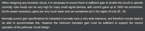
in regards to hfe ratings, keep in mind we are still dealing with an audio amp not an electron microscope in terms of accuracy and component tolerances (+/- 20/10/5/1 % vs +/ 0.01/0.001/0.0001 % type of thing). the circuit will determine how much hfe is needed for the task/output designed. upgrading hfe 100 to 500 would be overkill vs going from 400 to 100 may cause circuit/performace issues.

what is the universal sweet spot hfe, cant say that i have researched that question. establishing a +/- hfe for various circuit positions would be useful. once again, havent ventured down that road yet.


Screenshot 2026-06-13 at 10-58-01 Transistor Gain hFE hfe & Beta » Electronics Notes.png


*nice circuit sim (falstad) example and some benefits to high hfe.

 
going high or higher on frequency rating can be a bad thing. when using a transistor in the hifi spectrum 20hz-20khz there is no benefit to having a transistor upgraded from 1 mega-hertz to 100 mega-hertz. if anything having a higher ft increases the chances of high frequency oscillations and this isnt a radio-frequency amp.

if the transistor is limited to handling 1 mega-hertz it helps to ignore the mf/hf/vhf noise that can sabotage an audio amps performance.


**too many altium adverts on the page, although content informative

in regards to hfe ratings, keep in mind we are still dealing with an audio amp not an electron microscope in terms of accuracy and component tolerances (+/- 20/10/5/1 % vs +/ 0.01/0.001/0.0001 % type of thing). the circuit will determine how much hfe is needed for the task/output designed. upgrading hfe 100 to 500 would be overkill vs going from 400 to 100 may cause circuit/performace issues.

what is the universal sweet spot hfe, cant say that i have researched that question. establishing a +/- hfe for various circuit positions would be useful. once again, havent ventured down that road yet.


View attachment 3782014


*nice circuit sim (falstad) example and some benefits to high hfe.
I still have a lot to learn, so thank you for taking the time! Bottom line, I gather, is the 2SC2383 and 2SA1013 are legit replacements so I have those and the MJE15032/MJE15033 pairs on order.
 
Pre-drivers now fresh as well and everything still running the same. I didn't sub the overload protectors mentioned in post #123, didn't want to throw too much at it. Still no change from the #119 post readings nor did I expect them to. The numbers aren't perfect but at this point, I'm feeling close enough is fine. It's not the chips causing the slight difference, so wondering if it's a resistor or one of the non-electrolytic caps? Anyway, I'm tired of messing with it and ready to move on. Unfortunately, ran into another slight issue. This is a multi-voltage unit and the voltage selector completely fell apart. Searching the site, it appears to be a common problem and the part number is AKX-507. There is one available on a site called Spares2Repair. Anyone familiar with that site? Is it a legit replacement?

 
The numbers aren't perfect but at this point, I'm feeling close enough is fine.
far better than most, especially vs systems that are chaotically unstable for reasons unknown.

It's not the chips causing the slight difference, so wondering if it's a resistor or one of the non-electrolytic caps?
ocd perfectionist mode is possible. it will involve fine tuning the individual circuits to counteract the +/- variance outcome since a 1k resistor in the real world isnt 1k in all situations (loaded/unload).

output emitter resistor(s) could be adjusted up or down 10% or more i.e. 0.33r with 0.03r adjustment. essentially entering insanity mode since thermal highs and lows will skew the end result every time. count the number of components in the power supply circuit and each amp channel, tip of the iceberg in terms of +/- variables at all times.

for dc offset fine tuning, that might involve either padding the chip inputs so that the output countermeasure (like a servo) achieves the desired measurement number or tinkering with the few components interacting with pins 2/3 and 5/6 (r143, r145, c115, c117, c119).

[$$$] at the end of the day which is more important:

1) good enough and stable

vs

2) chasing schematic perfection and never taking time to enjoy the music

[$$$] = million dollar question
 

cant say that i am familiar with the site. keep in mind though original parts are also aged and if the quality/grade of plastic used for the component in question has a not so great shelf life... results may vary. typically the voltage selector doest see much mechanical action although some rare "traveling" cases probably exist.

wonder if any of the hardcore pioneer enthusiasts have donor parts they are willing to part with.
 

cant say that i am familiar with the site. keep in mind though original parts are also aged and if the quality/grade of plastic used for the component in question has a not so great shelf life... results may vary. typically the voltage selector doest see much mechanical action although some rare "traveling" cases probably exist.

wonder if any of the hardcore pioneer enthusiasts have donor parts they are willing to part with.
Or maybe a schematic that shows the wiring of that switch. I'm not against hardwiring as a last resort.
 
far better than most, especially vs systems that are chaotically unstable for reasons unknown.


ocd perfectionist mode is possible. it will involve fine tuning the individual circuits to counteract the +/- variance outcome since a 1k resistor in the real world isnt 1k in all situations (loaded/unload).

output emitter resistor(s) could be adjusted up or down 10% or more i.e. 0.33r with 0.03r adjustment. essentially entering insanity mode since thermal highs and lows will skew the end result every time. count the number of components in the power supply circuit and each amp channel, tip of the iceberg in terms of +/- variables at all times.

for dc offset fine tuning, that might involve either padding the chip inputs so that the output countermeasure (like a servo) achieves the desired measurement number or tinkering with the few components interacting with pins 2/3 and 5/6 (r143, r145, c115, c117, c119).

[$$$] at the end of the day which is more important:

1) good enough and stable

vs

2) chasing schematic perfection and never taking time to enjoy the music

[$$$] = million dollar question
Your words of wisdom are much appreciated! Good enough and stable is where I'm at, and your time and patience with me through all this is priceless. Likely would've given up without you holding me accountable
 
I'm not against hardwiring as a last resort.
i like the way you think, and it shows (reaction to post #138 as proof)

Likely would've given up without you holding me accountable
social/technical support via online forum can be beneficial for any & all who visit or revisit anytime in the future.

far too many projects are consumed by cyber-silence or digital ears and therefore fade into obscurity until another focused+motivated individual enters with a similar situation. which could be days/weeks/months/years/decades in the future. look no further than zombie threads that are brought back to life, still useful information being added.

helping another is also beneficial, especially since there is a +75/-25 chance the brand+model your working on (pioneer m-90) will be sitting on my bench at some point in time, oh the horror of an ulterior motive.

either way your success with your project benefits an unlimited number of others on planet earth (internet access required).

...now about sourcing parts or hard-wiring... have to do some digging and research. slightly distracted with current heathkit tube amp redesign/rebuild/re-cap/re-whatever.
 
Back
Top Bottom