• The move to the new server is done. There are some software and database maintenance updates in process. This has us passing the hat around to help out. We appreciate any donations. Seriously, even a dollar helps. The payment page may be found here - https://www.audiokarma.org/support.html

Pioneer M-90 Issue- need help.

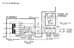
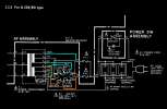
Found this in a manual for a Pioneer A-229/A-119 Power Amp that also show a AKX-507 voltage selector in it's parts breakdown. Any chance M-90 is wired the same? Found a post from AK member "hennessy" concerning the same M-90 selector who stated shorting pins 3 and 6 as well as 1 and 4 would do the trick for 120VAC. This diagram would confirm that the way I read it. Just don't want to kill myself or the unit shortin' the wrong combination.


Attachments

  • AKX-507.png
    AKX-507.png
    178.8 KB · Views: 9
Last edited:
*an example of akx-063 with mapped routing of conductors vs selection

photos of your systems wiring available? mains transformer model number?
 
AKX-507 finger painting.png
yeah, looks like 1&4 as well as 3&6 are the selector pairs for 120v. L1 color coded parallel route to neutral (txf pin-1 at 0v)
 
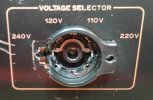
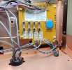
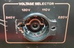
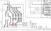
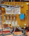
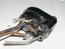
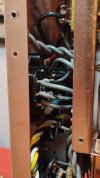
Not sure any of that matches up. This thing completely fell apart on me to the point I could determine exactly where the contacts were. Luckly I still have an old pic of the contacts when I tried to rebuild this a few months back. You can see one set of contacts have some arc burns so those obviously tied to the lower right 2 contacts on what's left of the socket. the wires tied to those contacts go to the power transformers. The other set of none burnt contacts would then go to the upper left contacts on the socket. Those go to pins 9 and 10 on the fuse assembly. That looks to match up with pins 4 and 7 on the other side of the fuse assy and on the schematic. Does that look right? Would you short those? Then again, can that schematic be used in this situation since it doesn't represent a muti voltage unit. There's no pin 9 or 10 on that schematic.
 

Attachments

  • 1.jpg
    1.jpg
    63.2 KB · Views: 12
  • IMG_20260625_171806933_PORTRAIT.jpg
    IMG_20260625_171806933_PORTRAIT.jpg
    65.2 KB · Views: 10
  • IMG_20260625_174813943.jpg
    IMG_20260625_174813943.jpg
    143.8 KB · Views: 12
  • Fuse Assy.JPG
    Fuse Assy.JPG
    98.2 KB · Views: 9
  • SCHE.JPG
    SCHE.JPG
    106 KB · Views: 11
Last edited:
From the service manuals I pulled down from hifi engine, I've attached the only 2 diagrams I have for the fuse assy and neither match what I have, nor do the schematics, so trying to nail down the actual circuit would be hard for me to figure out. However, in order to make this run on 120VAC I'm thinking I just need to short the pins on the socket as I've depicted below. Can I get an amen? If I pull the socket and connect the wires from the appropriate pins, can the rest of the wires on that socket be removed or set aside securely? They no longer need to be connected to anything for 120VAC- is that right?
 

Attachments

  • IMG_20260625_171806933_PORTRAIT.jpg
    IMG_20260625_171806933_PORTRAIT.jpg
    65.2 KB · Views: 1
  • Fuse Assy 2.JPG
    Fuse Assy 2.JPG
    103.5 KB · Views: 1
  • Fuse Assy.JPG
    Fuse Assy.JPG
    98.2 KB · Views: 1
Last edited:
Does that look right? Would you short those? Then again, can that schematic be used in this situation since it doesn't represent a muti voltage unit. There's no pin 9 or 10 on that schematic.
think of the schematic as a "suggested" roadmap vs indisputable roadmap, especially with vintage gear.

clerical errors happen more than a little as do incorrect silkscreen of components or their polarity. finding the 100% match service manual for the system in front of you can also be a chore, some brands have serial number range specified (can also be annoying too).

obviously the fully functional m-90 is the reference point to compare a schematic to, it works so it must be constructed/wired correctly (sometimes a dangerous assumption) . reverse engineering the voltage selector switch/socket should be relatively simple when mapping out what goes where and why.

in this case, the selector wheel and lining up what is jumped when selecting 120v. looks like the switch housing has an internal jumper going horizontally from one side to the other.

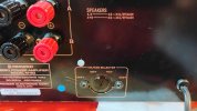
looking at photo #2 in post #144 shows the potential of completely deleting the voltage selector, possibly install a cosmetic cover labeled as 120v only or something. in photo #3 of the same post, wow that chassis mount selector/switch has seen better days.

following the wires between selector and pioneer fuse board awz1160 (guessing its a 6 or an 8) shows a few options for installing solder jumpers or direct bypass. nice clean large resolution photo definitely appreciated. my photos tend to be a point & click blunder only noticed when trying to post them after the fact.

carbon from arc'ing of selector contacts is concerning, especially about previous owner(s).
 
think of the schematic as a "suggested" roadmap vs indisputable roadmap, especially with vintage gear.

clerical errors happen more than a little as do incorrect silkscreen of components or their polarity. finding the 100% match service manual for the system in front of you can also be a chore, some brands have serial number range specified (can also be annoying too).

obviously the fully functional m-90 is the reference point to compare a schematic to, it works so it must be constructed/wired correctly (sometimes a dangerous assumption) . reverse engineering the voltage selector switch/socket should be relatively simple when mapping out what goes where and why.

in this case, the selector wheel and lining up what is jumped when selecting 120v. looks like the switch housing has an internal jumper going horizontally from one side to the other.

looking at photo #2 in post #144 shows the potential of completely deleting the voltage selector, possibly install a cosmetic cover labeled as 120v only or something. in photo #3 of the same post, wow that chassis mount selector/switch has seen better days.

following the wires between selector and pioneer fuse board awz1160 (guessing its a 6 or an 8) shows a few options for installing solder jumpers or direct bypass. nice clean large resolution photo definitely appreciated. my photos tend to be a point & click blunder only noticed when trying to post them after the fact.

carbon from arc'ing of selector contacts is concerning, especially about previous owner(s).
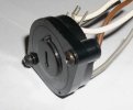
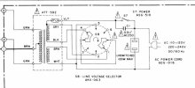
Included a better pic of the fuse assy. Bottom pins from left to right numbered 9, 10, 11, 12. I noticed that arcing a few months back when I rebuilt the switch and guessed the burns were the result of a loss of integrity in the switch. During the recap I was having intermittent power issues and isolated it to that switch. When I rebuilt it, I swapped those contacts. Since there's still no burns on the other contact now after turning this thing on an off a bunch of times since, I'm hopping that's all it was. A bit frustrated it disintegrated after the work I put into it. It was still working fine, but I noticed some new cracks after work my current issue and when I went to take a closer look.... That internal jumper you mentioned has no connection to anything. No pins to wire wrap to and no connection to the other pins either. However, it would short the 2 rotating contacts together in the 220 or 240 positions. I found an AKX-063 on ebay I'm going to give a try. Seller says it came off a Pioneer SG-9800. Pulled the schematic and included a excerpt below. Schematic shows that same internal jumper as an external wire connection but if you look at the back of the actual switch, there's just some nubs there with no connection. Will keep you posted.
1782682720150.jpeg
1782683165383.jpeg
 

Attachments

  • AKX-063 1.JPG
    AKX-063 1.JPG
    24.9 KB · Views: 3
  • AKX-063 2.JPG
    AKX-063 2.JPG
    17.6 KB · Views: 3
  • AKX-063.JPG
    AKX-063.JPG
    41.6 KB · Views: 3
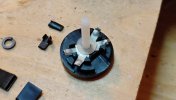
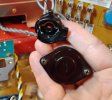
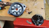
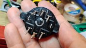
Finished the effort to replace the AKX-507 switch with an AKX-063 and it turned out well, but not without some workarounds. You can see the replacement is larger with a more robust casing and contacts which is nice. The contact setup is exactly the same as the original switch, but the 4 switch positions are not and the directional arrow does not line up with the contacts like the original. So you can see in the pic with the opened switch I had to file down that triangle shaped tab (stopper) near the center pin so I had the right 4 switch positions I needed. Also had to add a new mark (pointer) on the switch cover to line up with the appropriate voltage selections. Only drawback is the switch rotates 360 degrees, so have to note that but otherwise it works and fits great. A very solid replacement. There’s also a pic of what’s left of the old switch. Now to get this thing back together.
 

Attachments

  • IMG_20260708_203943541.jpg
    IMG_20260708_203943541.jpg
    81 KB · Views: 8
  • IMG_20260709_180931230.jpg
    IMG_20260709_180931230.jpg
    109.7 KB · Views: 12
  • IMG_20260709_180130704.jpg
    IMG_20260709_180130704.jpg
    62.2 KB · Views: 11
  • IMG_20260709_180046210_HDR.jpg
    IMG_20260709_180046210_HDR.jpg
    66.8 KB · Views: 10
  • IMG_20260709_171735079.jpg
    IMG_20260709_171735079.jpg
    92.6 KB · Views: 7
  • IMG_20260708_205232360_HDR.jpg
    IMG_20260708_205232360_HDR.jpg
    89 KB · Views: 6
  • IMG_20260708_203958382.jpg
    IMG_20260708_203958382.jpg
    74.4 KB · Views: 6
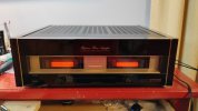
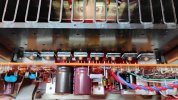
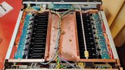
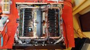
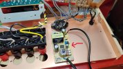
Calling this effort complete. A few pics with the new power transistors installed. New pre-drivers as well but not as impressive to look at. Happy I got that upgrade along with replacing all the old fusible resistors. My lack of experience wasted time and money chasing the wrong things but learned from it. In the one open top pic you can see 2 of the 4 mini 12vdc fans mounted to the inside of the bottom cover, just under the heat syncs. They're tied to 120VAC to 12VDC converter mounted there on the inside of the back panel. It's wired to pins 3 and 4 circled on the fuse assy where I get 120VAC once the power switch is turned on. The converter has a pot to control fan speed which helps since the fans are a little noisy ruing full speed. The setup actually helps it run a bit cooler. Big shout out to sae-7125 for sticking with me- very much appreciated!
 

Attachments

  • IMG_20260711_193643162.jpg
    IMG_20260711_193643162.jpg
    53.6 KB · Views: 7
  • IMG_20260617_165923871_HDR.jpg
    IMG_20260617_165923871_HDR.jpg
    101.4 KB · Views: 4
  • IMG_20260711_151219641_HDR.jpg
    IMG_20260711_151219641_HDR.jpg
    118.3 KB · Views: 5
  • IMG_20260711_191137684.jpg
    IMG_20260711_191137684.jpg
    109.3 KB · Views: 5
  • IMG_20260709_171735079.jpg
    IMG_20260709_171735079.jpg
    93.9 KB · Views: 4
  • IMG_20260628_171156310.jpg
    IMG_20260628_171156310.jpg
    131.2 KB · Views: 8
My lack of experience wasted time and money chasing the wrong things but learned from it.
and yet, what you have learned is truly priceless. especially since your home laboratory helped immensely with the self-study that was achieved. i dont know of a community college nor university that can compete with that, well done sir.

look no further than the "thousands" of views your project has created, in a thread on a forum that should outlast both of us. definitely a worthwhile contribution to the global digital society.

2 of the 4 mini 12vdc fans mounted
now were talking, greatly improved thermal management. i have found that the cfm of running a 24v dc fan at 12v or 12v dc fan at around 8v to be useful. some of the computer/gamer pwm setups can be worthwhile.

one of the class-d/digital-ish amps i have on the bench, topping or nobsound or something, is enjoying a relatively silent blower on top. even when/after exercising the amp at full volume (around 120w/ch rms) the chassis continues to be around room temp.

Big shout out to sae-7125 for sticking with me- very much appreciated!
a rare treat, since i am relatively invisible in a crowd online or off.

your documented life experience is of great. the photos amplify the content even more.

time for you to enjoy a few thousand hours of music. dont forget to do an update after a week or month of daily use. although speaker shopping tends to be a side-effect of constant music enjoyment/therapy.

cheers
 
Thanks! And I'd like to add this after taking a few things to vintage techs who told me, "I don't have the time or it can't be fixed." If you love the hobby and have run out of options, do not underestimate you're ability to fix something- especially if you have a little electronics/tinkering background. Yea, it may be a little intimidating but I am blown away by what I've been able to fix with a VOM, a DB tester, and help from folks on this site along with a lot of patience and little humility. :)
 
Back
Top Bottom