• The move to the new server is done. There are some software and database maintenance updates in process. This has us passing the hat around to help out. We appreciate any donations. Seriously, even a dollar helps. The payment page may be found here - https://www.audiokarma.org/support.html

QSilver

Super Member
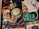
Seeing as this is a Pioneer chip, I figured the best place to say this was here. I've been working on a PL-630 and after some reworking and repairs, discovered that the PD1003 oscillator chip was (mostly) dead, and the motor just gently bounced back and forth. I confirmed it was the earlier stages of the chip that had failed by injecting the 750Hz reference into TP1 which got the motor to run again, so, confident that the rest of the deck was good, I set about researching the PD1003 chip and its functions and how to make a replica.

To cut a long story short, I've now completed my first revision of the replacement circuit board. This board replicates every single feature required for the PL-630 and is a drop in replacement. Although larger than the original, there is plenty of room to install it. I have built, tested and now run the new circuit in the PL-630 which is so far, running flawlessly. I don't know what the original IC current draw was, but mine is 7mA and has been designed to use almost totally through-hole components with an exception of a SMD divider IC that is required for Quartz Lock.

If anyone is interested in this, I can show some pictures. I know this chip was used in a lot of designs and I'm confident I can rework it for use in the CT-F1250 cassette deck, and any other Pioneer Turntable that used the IC. Perhaps I can even further miniaturise the circuit - however, my original brief for myself was through hole components as much as possible.

If you need one or are interested, please comment!
 
Register to hide this ad
Seeing as this is a Pioneer chip, I figured the best place to say this was here. I've been working on a PL-630 and after some reworking and repairs, discovered that the PD1003 oscillator chip was (mostly) dead, and the motor just gently bounced back and forth. I confirmed it was the earlier stages of the chip that had failed by injecting the 750Hz reference into TP1 which got the motor to run again, so, confident that the rest of the deck was good, I set about researching the PD1003 chip and its functions and how to make a replica.

To cut a long story short, I've now completed my first revision of the replacement circuit board. This board replicates every single feature required for the PL-630 and is a drop in replacement. Although larger than the original, there is plenty of room to install it. I have built, tested and now run the new circuit in the PL-630 which is so far, running flawlessly. I don't know what the original IC current draw was, but mine is 7mA and has been designed to use almost totally through-hole components with an exception of a SMD divider IC that is required for Quartz Lock.

If anyone is interested in this, I can show some pictures. I know this chip was used in a lot of designs and I'm confident I can rework it for use in the CT-F1250 cassette deck, and any other Pioneer Turntable that used the IC. Perhaps I can even further miniaturise the circuit - however, my original brief for myself was through hole components as much as possible.

If you need one or are interested, please comment!
I own 2 pioneer PL50L II and they do have the PD1003 chip. I have a problem on both of them with a little rattling whet the platter starts and if it touched during rotation. I wonder is this is due to e fault-ish chip. Anyway, I would love to test your equivalents. Please mail me if you can.
 
This is a pretty cool project. Problems like these are becoming more common, with custom IC's increasingly showing age related failures. Technics had a (Matsushita) IC used as the PLL on several of their early CD players, including the SL-P1200 and 1300 (both sought after as collectibles) and it appears that over time almost every one of these IC's is destined to fail, turning these units into fancy boat anchors. It is my hope someone will take up the cause and engineer a replacement part (I lack the skill set to do so, or I'd probably spearhead such an effort). Much respect to you for working up a solution that saved your PL-630.
 
Ponieważ to układ Pioneera, uznałem, że najlepiej o tym wspomnieć. Pracowałem nad PL-630 i po kilku przeróbkach i naprawach odkryłem, że układ oscylatora PD1003 był (prawie) niesprawny, a silnik tylko delikatnie drgał w przód i w tył. Potwierdziłem, że to wcześniejsze etapy układu uległy awarii, podając napięcie referencyjne 750 Hz do TP1, co ponownie uruchomiło silnik. Upewniwszy się, że reszta decka jest sprawna, zabrałem się za badanie układu PD1003, jego funkcji i sposobu wykonania repliki.

Krótko mówiąc, ukończyłem już pierwszą wersję zamiennej płytki drukowanej. Ta płytka powiela wszystkie funkcje wymagane w PL-630 i stanowi doskonały zamiennik. Chociaż jest większa od oryginału, oferuje mnóstwo miejsca na jej instalację. Zbudowałem, przetestowałem i uruchomiłem nowy układ w PL-630, który jak dotąd działa bez zarzutu. Nie wiem, jaki był pobór prądu przez oryginalny układ scalony, ale mój wynosi 7 mA i został zaprojektowany tak, aby wykorzystywać niemal wyłącznie elementy przewlekane, z wyjątkiem układu scalonego dzielnika SMD, który jest wymagany do blokady kwarcowej.

Jeśli ktoś jest zainteresowany, mogę pokazać kilka zdjęć. Wiem, że ten układ był używany w wielu projektach i jestem pewien, że mogę go przerobić do magnetofonu kasetowego CT-F1250 i dowolnego innego gramofonu Pioneer, który korzystał z tego układu. Być może uda mi się jeszcze bardziej zminiaturyzować układ – jednak moim pierwotnym założeniem było zastosowanie jak największej liczby elementów przewlekanych.

Jeśli potrzebujesz takiego produktu lub jesteś zainteresowany, napisz komentarz!
Jestem zainteresowany Twoim rozwiązaniem.
Proszę o więcej informacji na temat tego zamiennika.
 
Seeing as this is a Pioneer chip, I figured the best place to say this was here. I've been working on a PL-630 and after some reworking and repairs, discovered that the PD1003 oscillator chip was (mostly) dead, and the motor just gently bounced back and forth. I confirmed it was the earlier stages of the chip that had failed by injecting the 750Hz reference into TP1 which got the motor to run again, so, confident that the rest of the deck was good, I set about researching the PD1003 chip and its functions and how to make a replica.

To cut a long story short, I've now completed my first revision of the replacement circuit board. This board replicates every single feature required for the PL-630 and is a drop in replacement. Although larger than the original, there is plenty of room to install it. I have built, tested and now run the new circuit in the PL-630 which is so far, running flawlessly. I don't know what the original IC current draw was, but mine is 7mA and has been designed to use almost totally through-hole components with an exception of a SMD divider IC that is required for Quartz Lock.

If anyone is interested in this, I can show some pictures. I know this chip was used in a lot of designs and I'm confident I can rework it for use in the CT-F1250 cassette deck, and any other Pioneer Turntable that used the IC. Perhaps I can even further miniaturise the circuit - however, my original brief for myself was through hole components as much as possible.

If you need one or are interested, please comment!
Hello,

I am interested in your solution.
Please send me more information about this replacement.
 
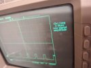
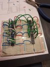
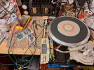
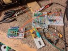
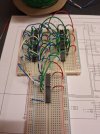
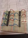
Thanks for your support! Its taken me much longer than I wanted, but I have some photographs here of the Pre-PCB prototype when I was building up the various modules of circuitry required and testing all my research out. It was quite a sight when, after putting everything together, I connected it up to the PL-630 and it began to spin perfectly.

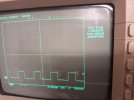
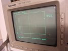
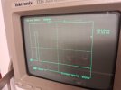
These show some of the initial testing where I was checking that I was getting the right number of initial divisions of frequency and that they were toggling between one and other other in the right sequence. It was quite the rats nest! But it ran well!
 

Attachments

  • 14af2035-2b13-4eb8-a291-769d9815e531.jpg
    14af2035-2b13-4eb8-a291-769d9815e531.jpg
    58.7 KB · Views: 25
  • 90998081-b67c-44cb-aa32-af76623db0ee.jpg
    90998081-b67c-44cb-aa32-af76623db0ee.jpg
    118 KB · Views: 28
  • 20250622_212222.jpg
    20250622_212222.jpg
    196.2 KB · Views: 26
  • 20250607_221844.jpg
    20250607_221844.jpg
    226.7 KB · Views: 26
  • 51280d2e-0372-4dab-9197-5a7849d812bb.jpg
    51280d2e-0372-4dab-9197-5a7849d812bb.jpg
    111.1 KB · Views: 22
  • 2752e57f-1366-4f41-8439-79b7f1574d38.jpg
    2752e57f-1366-4f41-8439-79b7f1574d38.jpg
    110.3 KB · Views: 22
  • 53f84f40-84b7-45cc-a560-e3c11a85e1c3.jpg
    53f84f40-84b7-45cc-a560-e3c11a85e1c3.jpg
    72.3 KB · Views: 24
...and here is the final V1 design layout! As you can see, it is much larger than the IC and its board. However, it is all through-hole technology except for the initial division IC. I was considering an SMD version and for other turntables and other cassette deck hall motor designs, that might be necessary. I had a few of these boards made up, and for any turntable or any other device that uses the original Pioneer PD1003 IC, this board will work. All the logic H/L signals fed from the 33/45 Quartz/RC toggles are received and processed the same way. As the PL-630 doesn't have a stroboscope, I haven't populated that part but I do have a provision.

If this was to be used in the CT-F1250, some of the division steps would need to be changed but again, this could be done on a new revision if there is enough interest. My main goal was to just get everything that the PL-630 needed going first, and I've succeeded with that. With the core of that done, any other adjustment for another system or even a fully generic PCB is possible.

The new PCB has two mounting points where the original PCB mounted and one additional one that needs a small hole drilled into the chassis and then tapped, and a standoff fitted.

This took me around 3-6 months to develop and test, so I hope no one minds that I am happy to make this available for a reasonable cost. I'd love to make it publicly available, but at the moment, I have to make ends meet and its not at a stage where it could just be picked up and put into anything with that IC. I'll keep developing it if there is interest and if you'd like one, let me know!
 

Attachments

  • 20250704_184904.jpg
    20250704_184904.jpg
    181.2 KB · Views: 35
  • 20250607_221908.jpg
    20250607_221908.jpg
    67.4 KB · Views: 32
  • 20250607_221926.jpg
    20250607_221926.jpg
    68.2 KB · Views: 31
Remarkable efforts. I am chatting with you via message just wanted to let you know I read this post. I am currently having a problem with my pd1003 ic.
 
QSilver, I am very interested in acquiring one of your boards. I am wondering if it would be cost effective, considering my customer is willing to spend a certain maximum amount of money for me to repair his PL-630. What is your price?
 
Seeing as this is a Pioneer chip, I figured the best place to say this was here. I've been working on a PL-630 and after some reworking and repairs, discovered that the PD1003 oscillator chip was (mostly) dead, and the motor just gently bounced back and forth. I confirmed it was the earlier stages of the chip that had failed by injecting the 750Hz reference into TP1 which got the motor to run again, so, confident that the rest of the deck was good, I set about researching the PD1003 chip and its functions and how to make a replica.

To cut a long story short, I've now completed my first revision of the replacement circuit board. This board replicates every single feature required for the PL-630 and is a drop in replacement. Although larger than the original, there is plenty of room to install it. I have built, tested and now run the new circuit in the PL-630 which is so far, running flawlessly. I don't know what the original IC current draw was, but mine is 7mA and has been designed to use almost totally through-hole components with an exception of a SMD divider IC that is required for Quartz Lock.

If anyone is interested in this, I can show some pictures. I know this chip was used in a lot of designs and I'm confident I can rework it for use in the CT-F1250 cassette deck, and any other Pioneer Turntable that used the IC. Perhaps I can even further miniaturise the circuit - however, my original brief for myself was through hole components as much as possible.

If you need one or are interested, please comment!
Hi , Im interested in your Pd1003 Solution , need for Pl560 turntable and Ctf 1250 tape deck .
 
Back
Top Bottom