• The move to the new server is done. There are some software and database maintenance updates in process. This has us passing the hat around to help out. We appreciate any donations. Seriously, even a dollar helps. The payment page may be found here - https://www.audiokarma.org/support.html

Pioneer SA-800 Recap

C7 and C8 are 7uF? Look again inside. Maybe 4.7uF or 47uF, I do not downloaded the schematics. Another tip: when you up with voltage you can do for one ore two steps. E.g. 100uF at 6V you can choose 100uF at 16V or 25V. Another tip: a modern capacitor is smaller then old one (in dimensions - because of new technology). So you don't have to go at 100V.
In my oppinion you should go with best caps in PS stage. They are a reservoir for your unit.
 
I have the schematic now, C7&C8 are 4.7uF/25V. Your list looks better now but can be improved. Let start with power supply. FG are good caps for audio but I find UPW series more suitable for this destination (low impedance). They are rated at 105°C. United Chemicon has good capacitors for PS but let go with Nichicon. When you do a recap start with PS first then check what you have done and after you can go with another board like protection.
 
I have the schematic now, C7&C8 are 4.7uF/25V. Your list looks better now but can be improved. Let start with power supply. FG are good caps for audio but I find UPW series more suitable for this destination (low impedance). They are rated at 105°C. United Chemicon has good capacitors for PS but let go with Nichicon. When you do a recap start with PS first then check what you have done and after you can go with another board like protection.

Ah, that must have been a typo, thanks for catching it. I updated the list again, now using UPWs for the power supply.
 
My recommendations: please check again.

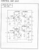
Head Amp Unit – Capacitors

  • C15 (CEA 101P 35: 100uF, 35V, 85°C, d:18mm, pins:10mm): UKZ2A101MHM1TN (100V, 16mm) - UKZ1H101MHM (50V)
Control Amp Unit – Capacitors

C11 (CEA 100P 25: 10uF, 25V, d:7mm, pins:6mm): UKZ2A100MPM1TD (10uF, 100V) or UFG1H100MDM (50V, 2mm space)
C12 (CEA 100P 25: 10uF, 25V, d:7mm, pins:6mm): UKZ2A100MPM1TD (10uF, 100V) or UFG1H100MDM (50V, 2mm space)
C13 (CEA 100P 25: 10uF, 25V, d:7mm, pins:6mm): UKZ2A100MPM1TD (10uF, 100V) or UFG1H100MDM (50V, 2mm space)
C14 (CEA 100P 25: 10uF, 25V, d:7mm, pins:6mm): UKZ2A100MPM1TD (10uF, 100V) or UFG1H100MDM (50V, 2mm space)
C15 (CEA 500P 25: 220uF, 35V, d:13mm, pins:10mm): UKZ1H331MHM (330uF, 50V, 16mm) or UFG1H331MHM (330uF, 50V) - ckeck for clearance

Filter Unit – Capacitors
  • C11 (CEA 100P 16: 10uF, 16V, d:6mm, pins:5mm): UKZ2A100MPM1TD (10uF, 100V) or UFG1H100MDM (50V, 2mm)
  • C12 (CEA 100P 16: 10uF, 16V, d:6mm, pins:5mm): UKZ2A100MPM1TD (10uF, 100V) or UFG1H100MDM (50V, 2mm)
Main Amp Unit – Capacitors
  • C11 (CEA 220P 6: 22uF, 6V (current: 6.3V), 5mm): UKZ2A220MPM (100V) or UFG1E220MDM1TD (25V, 2 mm space)
  • C12 (CEA 220P 6: 22uF, 6V (current: 6.3V), 5mm): UKZ2A220MPM (100V) or UFG1E220MDM1TD (25V, 2 mm space)
Protector Unit – Capacitors
  • C3 (CEA 221P 10: 220uF, 10V, d:10mm, pins:6mm): UFG1C221MPM1TD (16V) or UPW1V221MPD (35V)
  • C4 (CEA 221P 10: 220uF, 10V, d:10mm, pins:6mm): UFG1C221MPM1TD (16V) or UPW1V221MPD (35V)
  • C5 (CEA 101P 16: 100uF, 16V, d:10mm, pins:6mm): UFG1V101MPM (35V) or UPW1J101MPD (63V)
Power Supply Unit – Capacitors
  • C5 (CEA 101P 50: 100uF, 50V, d:13mm, pins:10mm): UPW2A101MHD (100V) or UPW1J101MPD (63V)
 
As for transistors

Head Amp Unit – Semiconductors

  • Q1 (Transistor 2SC1000-BL): KSC1845FTA OK
  • Q2 (Transistor 2SC1000-BL): KSC1845FTA OK
  • Q3 (Transistor 2SC1000-BL, GR): KSC1845FTA OK
  • Q4 (Transistor 2SC1000-BL, GR): KSC1845FTA OK
  • Q5 (Transistor 2SC1000-BL, GR): KSC1845FTA OK
  • Q6 (Transistor 2SC1000-BL, GR): KSC1845FTA OK
Control Amp Unit – Semiconductors
  • Q3 (Transistor 2SC458LG): KSC1815YTA or KSC1845FTA
  • Q4 (Transistor 2SC458LG): KSC1815YTA or KSC1845FTA
  • Q5 (Transistor 2SC458LG): KSC1815YTA or KSC1845FTA
  • Q6 (Transistor 2SC458LG): KSC1815YTA or KSC1845FTA
Filter Unit – Semiconductors
  • Q1 (Transistor 2SC870-E or F): KSC1845FTA OK
  • Q2 (Transistor 2SC870-E or F): KSC1845FTA OK
Main Amp Unit – Semiconductors

I think I'll leave Q11~14 alone for now. Best ideea
  • Q1 (Transistor 2SA572-4B): KSA992FBU OK but be very carefull. Must be Hfe and Vbe matched
  • Q2 (Transistor 2SA572-4B): KSA992FBU OK
  • Q3 (Transistor 2SA572-4B): KSA992FBU OK
  • Q4 (Transistor 2SA572-4B): KSA992FBU OK
  • Q5 (Transistor 2SC627-1): KSC3503DSTU OK
  • Q6 (Transistor 2SC627-1): KSC3503DSTU OK
  • Q7 (Transistor 2SC497-0): KSC2383YTA NPN OK
  • Q8 (Transistor 2SC497-0): KSC2383YTA NPN OK
  • Q9 (Transistor 2SA497-0): KSC2383YTA PNP KSA1013
  • Q10 (Transistor 2SA497-0): KSC2383YTA PNP KSA1013
Protector Unit – Semiconductors
  • Q1 (Transistor 2SC983-0): KSC2383YTA
  • Q2 (Transistor 2SC983-0): KSC2383YTA
  • Q3 (Transistor 2SC945-R): KSC1845FTA
  • Q4 (Transistor 2SC945-R): KSC1845FTA
  • Q5 (Transistor 2SA572-4): KSA992FBU
  • Q6 (Transistor 2SC968-2): KSC2383YTA
  • Q7 (Transistor 2SC495P-Y): KSC2690AYS (may not fit), MJE181 or KSD794AYSTU
Power Supply Unit – Semiconductors
  • Q1 (Transistor 2SD234-0): KSC2073TU OK
  • Q2 (Transistor 2SC373): KSC2383YTA OK
I have to search for protector unit replacements
 
Last edited:
Thank you very much for the recommendations! I shall update the list.

I do have some more questions, if I may:
  • In may cases you recommend (physically) smaller capacitors that are a closer fit to the original voltage. Do you value similar voltage higher than similar dimensions?
  • For the protector unit you also recommend UPW rather than UFG. Is that for the same reason as in the power supply unit?
  • Regarding the control amp transistors, another member recommended the KSC1815 over the KSC1845. Do you have a particular reason for recommending it the other way round?
 
Last edited:
It is not necessary to go up to 100V for a 16V cap. Bigger voltage, bigger case. Sometimes,for aestethic you can go with bigger value. I know UKZ is a big cap, I am using them in my restoration like SX-727 here on AK.
1845 has better voltages and noise reduction than 1815. 1815 has a bigger Ic than 1845. If the schematic requires a high current you have to go with 1815. If not, 1845 works great. KSC1845 is a cheap transistor, I suggest to buy 100pcs for best matching.
UFG is an audio grade capacitor you don't need one there. Is nothing wrong to use FG , but I think is cheaper.
What device do you have for matching transistors? It is very important to have the same values in differential pair for Hfe and Vbe. I also suggest to buy 100pcs for KSA992, they are cheap and you can make pairs easily.
 
Last edited:
...you also recommend UPW rather than UFG. Is that for the same reason as in the power supply unit?...

For power supply or local decoupling/filtering duty (e.g., C15 on Head Amp Unit, W21-007), a low ESR capacitor type (e.g., Nichicon PW) is typically preferred. Also it is generally beneficial to increase the capacity of the filtering capacitors. There is no problem increasing the capacitance rating of the local decoupling/filtering capacitor (especially for small values less than 1000µF). IMO, a 2X-3X increase is acceptable for most small capacity capacitors whose purpose is solely DC filtering. In these cases, the extra load on the power supply transformer and diodes is inconsequential. More often than not, the original capacitance rating specified during manufacturing was often limited by capacitor technology of the day, the cost of component and the physical size (finite space available on the PCB).

Why increase the capacity of a power supply? It can be argued that the power supply is in the signal path, it's essentially in series with the output stage and hence does impact the sound of an amplifier. Nelson Pass uses the analogy of a water reservoir as the power supply and the output stage as the valve that controls the flow of the water: https://www.passdiy.com/project/articles/power-supplies. If you have a poor and/or inadequate supply, the quality and/or the quantity of water is affected. For an amplifier, a poor/failing power supply capacitor (e.g., low capacity, high ESR) may not be able to supply the voltage/current that the output stage is "asking" for. IMO, this is primarily why improving the power supply (e.g., increasing capacity, lowering impedance/ESR) often does impact/improve the sound of an amplifier.
 
In the signal path (e.g., C1/C2 and C5/C6 in the Head Amp Unit), many advocate the use of miniature stacked film capacitors (e.g, WIMA MKS2/MKS02 or Kemet R82) whenever possible, i.e., for capacitors that are ≤4.7µF. For larger values Nichicon ES bi-polar types can be used. This approach is largely supported by the work of Cyril Bateman examining the impact of capacitors on sound quality: https://linearaudio.nl/cyril-batemans-capacitor-sound-articles. He tested electrolytic capacitors extensively and demonstrated that in AC coupling, bipolar electrolytic capacitors have the lowest distortion/noise of all the electrolytic types (even the presence of a polarizing voltage) and that film capacitors are generally lower distortion/noise than electrolytic capacitors of any type.
 
SA-800 looks close to my SX-737 I am restoring now here:
https://audiokarma.org/forums/index.php?threads/pioneer-sx-727-phoenix.910550/

Looking in main amp unit you have there are two pairs Q1-Q3 and Q2-Q2 (2SA572) which are in differential stage of main amp. When you choose transistors for differential pairs their characteristics must be the same. Like twins I could say. So, you must have same gain (Hfe) and Vbe (voltage between emitter and base). For this goal you need an electronic device to measure these characteristics. The cheaper is a chinese one like this:
V4LWgfl.jpg

You can see the information about your transistor in test: if it is PNP or NPN, leads order (BCE in this particular case), B (beta) or Hfe it is the gain and Uf same with Ube.

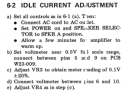
Trimmers are responsible for making adjustments on your amp in order to run in specs. In many cases these are ressponsible for amp damage. You have 2 on each channel, VR1 & VR2 for DC out adjustment and VR3 &VR4 for BIAS adjustment, according your Service Manual. I recommend to use multiturn ones. They are the blue ones from my picture
TvPAwiP.jpg
 
Hooray! It only took me a bit over 3 years but it's finally done, I just recapped the last of the boards and the amp is working great! I did have to bypass one of the tape monitor switches and lost a capacitor to bad reading skills (scary moment, that) but other than that it looks like a successful procedure. Thanks to everyone for your help!

There was one thing that I'm a bit curious about though: While going through the alignment procedure (using the fine new trimmers,!), the service manual says:

1697855364341.png
However, no matter what I do with VR3 and VR4, I cannot get close to 0.1V on these pins - the maximum I can get would be about 0.04V, right now I have them set to a value that produces 0.01V. Should I be worried about that?
 
In the schematic is stated 0.02V each side of the emitter resistors, which leads to a total of 0.04V....This would be a current of 40 milliamps as they are 1 Ohms together.

Most old amps are biased between 20 and 50 milliamps, so I would not sweat about it, although I would set it higher than the 10 millivolts/milliamps you have now, as whenever it gets TOO low (due temperature changes or voltage changes) the distortion will go up.

Maybe you did replace output transistors or their drivers, having a little bit different VBE compared to the old ones. The diode compensation circuit is rather inflexible, unfortunately. If you did not, it would be very interesting if anybody else DID reach the 100 mV /100 mA range in their SA800.
 
Ah great, thanks, I'll increase it to 20 mV then.

The output transistors would be the 4 large ones on the main amp, right? I didn't touch those, but yeah, I replaced their drivers.
 
if they will fit i would use film caps in all sizes up to 10 mfd to replace any e cap. you do that, and you wont need to replace that cap ever again
 
if they will fit i would use film caps in all sizes up to 10 mfd to replace any e cap. you do that, and you wont need to replace that cap ever again
Yeah next time I'll do that, for now I think I'll leave the new ones in there.

The amp has been running smoothly all day today, seems the whole thing was a success. The speaker relay appears a bit slow to disengage at times, but it seems to be improving.
 
the film caps at least to my ears, if in the signal path seem to make the sound much clearer. too bad the technology doesnt exist to make them small enough in larger capacitance values. or larger capacitance values in a lower rated voltage.
 
Back
Top Bottom