• The move to the new server is done. There are some software and database maintenance updates in process. This has us passing the hat around to help out. We appreciate any donations. Seriously, even a dollar helps. The payment page may be found here - https://www.audiokarma.org/support.html

Pioneer SA 9800 Power Supply Board Help

ok i have started the rebuild on the power supply board now its a case of locating where transistors what i go from mouser go i knew i should of pulled them out one at a time. its funny because i have two sa 9800 and both power boards look different one has four fuses the other has two so maybe some parts maybe different


The service manual has that information for anyone who understands how to find it.

The boards are named zzz-999 (awr-194), then the individual parts are Q3 Q4 Q10 as related above. IF there are major differences (like # of fuses) they will CHANGE the board number - LOOK for yours!!!!!

Then the layout diagram shows the board from the FOIL side with the parts locations (q3 etc) identified.

Turn the board over, locate the symbol printed on the board at that point, which will identify which leads go where. THEN look up on the data sheet which wires are what lead, and insert appropriately.

attachment.php
 

Attachments

  • finding_transistors.jpg
    finding_transistors.jpg
    58.5 KB · Views: 120
You can trust the markings on the PCB, the reverse overlay in the SM or what you remember pulling out at your own peril.

You should study the PSU schematic and crosscheck the component placement on the PCB and confirm your replacement pinout. (errors in schematics happen too, but not as often as silkscreen errors and service manual overlay errors IMO)
 
with the list of parts what mtf told me to order i have them is there any differences for the 2 fuse and 4 fuse versions for the parts? i have the 2 fuse version
 
with the list of parts what mtf told me to order i have them is there any differences for the 2 fuse and 4 fuse versions for the parts? i have the 2 fuse version

YOU need to get the BOARD NUMBER off the board, it will have the first three letters and a dash screen printed on it, then the following three numbers are stamped by a stamp pad type printing.

THEN we can see what's ON the board, IF we can find it in a service manual.

It is NOWHERE near time to spend money and order things.

The alternative is to visually identify the caps, and their (important!!) colors.
 
YOU need to get the BOARD NUMBER off the board, it will have the first three letters and a dash screen printed on it, then the following three numbers are stamped by a stamp pad type printing.

THEN we can see what's ON the board, IF we can find it in a service manual.

It is NOWHERE near time to spend money and order things.

The alternative is to visually identify the caps, and their (important!!) colors.


the caps are black on the one i am fixing and is 2 fuse power supply board not sure ofnumber will have to recheck .on my other sa 9800 they are in light blue nichicon
 
647-TVX2A221MCD
647-TVX2A221MCD
647-UPW1A470MDD6
647-UPW2A470MPD1TD
647-UPW2A470MPD1TD
647-UPW2A470MPD1TD
647-UPW2A470MPD1TD
647-UPW1H2R2MDD
647-UPW1H2R2MDD
647-UPW1V101MPD1TD
647-UPW1V101MPD1TD
512-KSC2690AYS
512-KSC2690AYS
512-KSA1013YBU
512-KSA1013YBU


512-KSC1845FTA
512-KSA992FBU
512-KSC2383YTA
512-KSA1013YBU
863-MJE15032G
863-MJE15033G
512-1n4004
512-1n4004
512-1n4004
512-1n4004
512-1n5233b
512-1n4148
512-1n4148
512-1n4004
512-1n4004
512-1N5247B

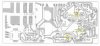
the parts listed above are what mtf told me to order the psu board i have is a AWR 194C as pictured im guessing this is a early sa 9800 with two fuses on psu board but are the fitments the same there is a list on page on as in where each part number must go can please someone ammend this for me for the AWR 194C board im working on or is it the same they all go in the same Q positions as listed like below or does it need to be changed for the board im working on im guessing some may need to be removed as there is four transistors on this list with heatsinks


awr-194 c2 220uf 80v ceb-axial 220 100 647-TVX2A221MCD
awr-194 c3 220uf 80v ceb-axial 220 100 647-TVX2A221MCD
awr-194 c4 47uf 10v cea 47 10 647-UPW1A470MDD6
awr-194 c7 47uf 63v cea 47 100 647-UPW2A470MPD1TD
awr-194 c8 47uf 63v cea 47 100 647-UPW2A470MPD1TD
awr-194 c9 47uf 63v cea 47 100 647-UPW2A470MPD1TD
awr-194 c10 47uf 63v cea 47 100 647-UPW2A470MPD1TD
awr-194 c13 2.2uf 50v cea 2.2 50 647-UPW1H2R2MDD
awr-194 c14 2.2uf 50v cea 2.2 50 647-UPW1H2R2MDD
awr-194 c15 100uf 35v cea 100 35 647-UPW1V101MPD1TD
awr-194 c16 100uf 35v cea 100 35 647-UPW1V101MPD1TD
awr-194 q1 2sc1735 pwr pass + 100v .5a .8w 512-KSC2690AYS to-126 30 to 300 hfe 130mhz to-92
awr-194 q2 2sc1735 pwr pass - 100v .5a .8w 512-KSC2690AYS to-126 30 to 300 hfe 130mhz to-92
awr-194 q3 2sa733 pwr darl + 50v 0.15a 0.25w 512-KSA1013YBU to-92L 40-700hfe 180mhz to-92
awr-194 q4 2sa904 pwr darl - 90v 0.05a 0.2w 512-KSA1013YBU to-92L 250hfe 150mhz to-92*c
awr-194 q5 2sk34 leave alone, unobtanium
awr-194 q6 2sk34 leave alone, unobtanium
awr-194 q7 2sc1914 fb ampl + 90v 0.05a 0.2w 512-KSC1845FTA (ln)to-92 250hfe 150mhz to-92*c
awr-194 q8 2sa904 fb ampl - 90v 0.05a 0.2w 512-KSA992FBU (ln)to-92 250hfe 150mhz to-92*c
awr-194 q9 2sc945 lv err amp + 50v 0.1a 0.25w 512-KSC2383YBU to-92L 600hfe 250mhz to-92
awr-194 q10 2sa733 lv err amp - 50v 0.15a 0.25w 512-KSA1013YBU to-92L 40-700hfe 180mhz to-92
awr-194 q11 2sd712 lv pass + 100 4a 30w 863-MJE15032G pnp to-220 55to300hfe 8mhz to-220
awr-194 q12 2sb682 lv pass - 100 4a 30w 863-MJE15033G pnp to-220 55to300hfe 8mhz to-220
awr-194 d1 sib01-02 power 200 1a 512-1n4004
awr-194 d2 sib01-02 power 200 1a 512-1n4004
awr-194 d3 sib01-02 power 200 1a 512-1n4004
awr-194 d4 sib01-02 power 200 1a 512-1n4004
awr-194 d5 xz-060 main zener 6v zener 0.5w 512-1n5233b
awr-194 d6 1s2473 fast 100v 0.1a 512-1n4148
awr-194 d7 1s2473 fast 100v 0.1a 512-1n4148
awr-194 d8 10E2 power 400v 1a 512-1n4004
awr-194 d9 10E2 power 400v 1a 512-1n4004
awr-194 d10 mz-177 shunt reg 17v zener 0.5w 512-1N5247B
 

Attachments

  • ScreenHunter_07 Oct. 18 12.00.jpg
    ScreenHunter_07 Oct. 18 12.00.jpg
    63.3 KB · Views: 65
Last edited:
well thats the board there as you can see on the bottom of page 2 of this thread i have started the recap i just want to know if transistors all go back in to there same Q positions as in the list mtf listed on page one or is it different for this awr 194C
 
Last edited:
hang on...

your picture = layout diagram that I copied from service manual and posted.

Yes.

careful, you have to use the symbols in the "upside down" diagram and the data sheet to figure out which way the new transistors point.
It doesn't help that they are all "in-line" transistor mounts.

attachment.php


These transistors are all ecb:
awr-194 q1 2sc1735 pwr pass + 100v .5a .8w 512-KSC2690AYS to-126 30 to 300 hfe 130mhz to-92
awr-194 q2 2sc1735 pwr pass - 100v .5a .8w 512-KSC2690AYS to-126 30 to 300 hfe 130mhz to-92
awr-194 q3 2sa733 pwr darl + 50v 0.15a 0.25w 512-KSA1013YBU to-92L 40-700hfe 180mhz to-92
awr-194 q4 2sa904 pwr darl - 90v 0.05a 0.2w 512-KSA1013YBU to-92L 250hfe 150mhz to-92*c
awr-194 q7 2sc1914 fb ampl + 90v 0.05a 0.2w 512-KSC1845FTA (ln)to-92 250hfe 150mhz to-92*c
awr-194 q8 2sa904 fb ampl - 90v 0.05a 0.2w 512-KSA992FBU (ln)to-92 250hfe 150mhz to-92*c
awr-194 q9 2sc945 lv err amp + 50v 0.1a 0.25w 512-KSC2383YBU to-92L 600hfe 250mhz to-92
awr-194 q10 2sa733 lv err amp - 50v 0.15a 0.25w 512-KSA1013YBU to-92L 40-700hfe 180mhz to-92

data from sheets:
512-KSA992FBU (ln)to-92 ecb 120v .05a .5w 100mhz 300-600hfe ----- Q8
512-KSC1845FTA (ln)to-92 ecb 120v .05a .5w 100mhz 300-600hfe ----- Q7
512-KSA1013YBU to-92L ecb 160v 1a .9w 50mhz 160-320hfe ----- Q3 Q4 Q10
512-KSC2383YTA to-92L ecb 160v 1a .9w 50mhz 160-320hfe ----- Q9
512-KSA1220AYS to-126 ecb 120/a160 1.2a 1.2w/20w 175mhz 35-320hfe ----- NONE
512-KSC2690AYS to-126 ecb 120/a160 1.2a 1.2w/20w 175mhz 35-320hfe ----- Q1 Q2


these transistors are difficult to reverse:
awr-194 q11 2sd712 lv pass + 100 4a 30w 863-MJE15032G pnp to-220 55to300hfe 8mhz to-220
awr-194 q12 2sb682 lv pass - 100 4a 30w 863-MJE15033G pnp to-220 55to300hfe 8mhz to-220

data from sheets:
863-MJE15033G pnp to-220 bce 250v 8a 50w 30mhz 70hfe --- Q12
863-MJE15032G npn to-220 bce 250v 8a 50w 30mhz 70hfe ---- Q11


OMG :yikes: :tears:
and looking at the picture, it was TOO LATE:
awr-194 q5 2sk34 leave alone, unobtanium
awr-194 q6 2sk34 leave alone, unobtanium
You pulled them OUT of the sockets.
ONE PART AT A TIME GETS PULLED AND IMMEDIATELY REPLACED. NOT ALL OF THEM ALL AT ONCE!!!!!!!!!!!!

Leave alone means leave alone. sigh...

This post is NOT finished until this line has been removed!!!!!!!!!!!!!!!!!!!!!!!!!!!
 
Last edited:
WAIT, I've been working on that last post

you guys jump too damn fast... I can't even hit the can...

just blindly boldly charging... into the minefield :yikes:

hang on means hang on!!!

I'm in a DIFFERENT place, on a DIFFERENT computer!!!!
 
I'm going cross eyed trying to relate the two posted pictures/diagrams together visually, for your Q9 question.

yes, q9 is the c2383
 
Cheers mark this board is proving a right pig to rebuild the back of the pcb in some spots is peeling can you send me a private message as to prices for your rebuilds fo sa 9800 as i know a few people what are very interested
 
any way of testing the psu board without switching on to make sure all caps n transistors have been installed correctly variac maybe? dnt want to fry anything
 
Back
Top Bottom