• The move to the new server is done. There are some software and database maintenance updates in process. This has us passing the hat around to help out. We appreciate any donations. Seriously, even a dollar helps. The payment page may be found here - https://www.audiokarma.org/support.html

Pioneer SA-9800 - what to do?

Now i know how to find the right way to install the new transistors. Just need to see if the schematics is the same as the assembled boards where they show E B C and then look in the datasheets for the new ones. No problem there.

Just remembered that it has a relay, replace it? If so with what?
 
I have found a couple of threads with some sort of parts list. Will go from there.

I thought the display just showed what the amp is doing. What source and VU meters. And when i look at the schematic i can see that it takes signal from the speaker selector but the speakers will still get the power. I can't find how the display actually has anything to do with the sound.

All the display is (and this is from working with earlier models so it may be conjecture for the Floroscan's) a digital version of a volt meter that has been "calibrated" for watts. It's just an indication of how many volts the amp is pushing to the speakers. It won't affect the sound quality or speaker operation.

Larry
 
The unit is now standing on my work bench, well most of it since it is in 1000 parts.

It has some rust on it, nothing to serious but it certainly doesn't look good. I have disassembled the whole chassi and i think i'm gonna paint it all black. I will take care of the rust tomorrow and hopefully i can start painting on Sunday.
I will repaint the whole chassi, the transformers and the metal cover.

I didn't test it before i took it all apart but nothing is burnt or strange so i think it will work. I really can't wait to hear it!

I have cleaned all the switches, relay etc. The relay is fine so that don't need replacement.

I will order all the transistors, capacitors, trimmers and so on hopefully next week so when it is ready to be put back together i can change the things i need to change. I don't know if i will order the 4 filter caps since they are quite expensive.

While i was taking it apart i damaged one of the micas for the output transistors, what should i do? I can't find any that fits.
 
Last edited:
The unit is now standing on my work bench, well most of it since it is in 1000 parts.

It has some rust on it, nothing to serious but it certainly doesn't look good. I have disassembled the whole chassi and i think i'm gonna paint it all black. I will take care of the rust tomorrow and hopefully i can start painting on Sunday.
I will repaint the whole chassi, the transformers and the metal cover.

I didn't test it before i took it all apart but nothing is burnt or strange so i think it will work. I really can't wait to hear it!

I have cleaned all the switches, relay etc. The relay is fine so that don't need replacement.

I will order all the transistors, capacitors, trimmers and so on hopefully next week so when it is ready to be put back together i can change the things i need to change. I don't know if i will order the 4 filter caps since they are quite expensive.

While i was taking it apart i damaged one of the micas for the output transistors, what should i do? I can't find any that fits.

I would shy away from painting the entire chassis if I were you. It uses numerous points as grounds, hence bare metal is key. Post some photos of the rust. If it is not too bad, clean it up, no paint.
 
While i was taking it apart i damaged one of the micas for the output transistors, what should i do? I can't find any that fits.

the hole to hole dimensions is 24.4 mm on those micas.

those are called mt-200

search on ebay for mt-200 mica and you will get a few choices. out of Hong Kong. They are not that common anymore...
 
Here is a couple of pictures of the rust. As you can see most of it is cleaned.
I disconnected two or three grounds but i have marked them up so i know where they need to be so when i paint i won't paint those areas. As i see it paint won't be any trouble if all the grounds are bare metal.
http://imageshack.us/f/189/otug.jpg/
http://imageshack.us/f/856/4z2h.jpg/

Yea, found a couple of the auctions. I also found something similar on a auction site in Sweden, 35x19 with a hole dimension of 25mm. Would they work?
 
Last edited:
Here is a couple of pictures of the rust. As you can see most of it is cleaned.
I disconnected two or three grounds but i have marked them up so i know where they need to be so when i paint i won't paint those areas. As i see it paint won't be any trouble if all the grounds are bare metal.
http://imageshack.us/f/189/otug.jpg/
http://imageshack.us/f/856/4z2h.jpg/

Yea, found a couple of the auctions. I also found something similar on a auction site in Sweden, 35x19 with a hole dimension of 25mm. Would they work?

Damn. You really have that thing stripped down. I thought I was bad when I did my SX-3900... Yeah, I would leave the chassis as it is. Unless you just want to paint it. I am not a fan of painting these amps/receivers. Especially black. Silver... might not be bad. So long as you are cognizant of the ground points. But it looks good as is now, and you won't even se most of that chassis once assembled.
 
I have primed everything except cover and the transformers. I will start painting tomorrow. The cover will have to wait until i got the amplifier working.
 
You can split one of the undamaged mica insulators. Just pry on the edge with your fingernail. If it breaks, no matter, you needed to order new ones anyway.
 
You can split one of the undamaged mica insulators. Just pry on the edge with your fingernail. If it breaks, no matter, you needed to order new ones anyway.

That is how i broke the first one and i'll guess it would work but when i'm repainting the chassi i like to keep everything as best as possible so i will get new ones.
 
Do you have any platers nearby? You could get a fresh coat of zinc or whatever they recommend electroplated on... It's THAT stripped down.... :D
 
Do you have any platers nearby? You could get a fresh coat of zinc or whatever they recommend electroplated on... It's THAT stripped down.... :D

My plan at first was to get it professional painted or plated but i can't find any that does that any more (for money someone can afford). It is very sad but i think my black paint job will be quite good. At least it will look better than rust.

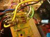
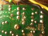
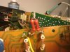
Found a strange modification. R5 (power supply) has been replace with two 1.2k resistors in series. And D1 (protection board) has been cut away from R5-6, C3 and the 8-s terminal and connected between those 1.2k resistors. Anyone have an idea why someone would do that?
 
Looks like somebody replaced the protection relay with a relay with a lower voltage coil?

what is the voltage printed on the relay?
 
post a picture of the cuts.

long explanation, here's a short version - C3 KICKS the relay over, then it is held with lower R6 current. Bad c3 no kick. relay buzzes but doesn't pull in.

sounds like some strange work around, done by unfathomable thought processes.
 
Here is three pictures to tell the stories.
As you also may notice C3 and R6 are not mounted in their sockets for some reason but it does look like factory work.
 

Attachments

  • DSC00170.jpg
    DSC00170.jpg
    86.3 KB · Views: 227
  • DSC00171.JPG
    DSC00171.JPG
    220.2 KB · Views: 118
  • DSC00172.JPG
    DSC00172.JPG
    194.4 KB · Views: 119
The protection circuitry has been gutted and the relay is apparently forced on continuously.

This is a SERIOUS danger that must be corrected, HOUSE FIRES have started because of abominations like this.

If I knew that a professional did this, I would run him out of business.

I would take an amateur's soldering iron away from him, and notify his insurance company.

This guy knew just enough to be dangerous. :gigglemad

The really frightening thing is that those resistors look like Pioneer factory resistors, so we may have to find out where he stole them from.
 
The protection circuitry has been gutted and the relay is apparently forced on continuously.

This is a SERIOUS danger that must be corrected, HOUSE FIRES have started because of abominations like this.

If I knew that a professional did this, I would run him out of business.

I would take an amateur's soldering iron away from him, and notify his insurance company.

This guy knew just enough to be dangerous. :gigglemad

The really frightening thing is that those resistors look like Pioneer factory resistors, so we may have to find out where he stole them from.

I have removed the 3 transistors and 2 capacitors and they were untouched, just the diode that has been modified.

I will start testing some transistors later when i have painted all the things.
 
While i was taking it apart i damaged one of the micas for the output transistors, what should i do? I can't find any that fits.

How about these?

SA-9800-11.jpg


They are Mouser part number 951-SP900S-009-00105, I found them by accident when looking for some insulators for replacement output transistors for my own SA-9800 thread. The originals turned out to be fine, and I ended up using the replacements in an SA-7800 that I fixed with Mark's help.

Your thread has given me the inspiration to go and get my SA-9800 out of storage. It's been sitting in there since September of last year, I got around to restoring the power supply board, and one of the power amp boards to get it to come out of protection. However, the one board has resistors on it that I mistakenly "upgraded" thinking that I was doing a good thing by using higher wattage ones. Not so, there are resistors in these amps that were designed to go pop in order to save other components in the circuit, so I will be putting these back to factory specs.

If my 9800 thread can help you in any way, you can find it here :

http://www.audiokarma.org/forums/showthread.php?t=420407

Lee.

 
How about these?

SA-9800-11.jpg


They are Mouser part number 951-SP900S-009-00105, I found them by accident when looking for some insulators for replacement output transistors for my own SA-9800 thread. The originals turned out to be fine, and I ended up using the replacements in an SA-7800 that I fixed with Mark's help.

Your thread has given me the inspiration to go and get my SA-9800 out of storage. It's been sitting in there since September of last year, I got around to restoring the power supply board, and one of the power amp boards to get it to come out of protection. However, the one board has resistors on it that I mistakenly "upgraded" thinking that I was doing a good thing by using higher wattage ones. Not so, there are resistors in these amps that were designed to go pop in order to save other components in the circuit, so I will be putting these back to factory specs.

If my 9800 thread can help you in any way, you can find it here :

http://www.audiokarma.org/forums/showthread.php?t=420407

Lee.

They look like they would fit. I have placed a bid on a auction that ends in 2 hours that has micas that should fit. But if i don't win them i sure will order those from Mouser!

Higher wattage isn't always better since the companies use there own stuff for a reason. I will agree that a 9800 has a lot of those so you will need to have a good look in the service manual.

A made a big mistake painting all those things black. Yesterday i painted the primer and let it dry over night. Today i cleaned all the things VERY long so no dust would ruin the black paint. Guess what happen? Some of the things now has a lot of small dots where the paint couldn't stick due dust or whatever. It isn't so bad but i will have to fill those dots later on. It is really annoying since everything has been going so well. :tears:
 
Back
Top Bottom