• The move to the new server is done. There are some software and database maintenance updates in process. This has us passing the hat around to help out. We appreciate any donations. Seriously, even a dollar helps. The payment page may be found here - https://www.audiokarma.org/support.html

Pioneer SA-9800 - what to do?

Well the micas fit like a glove. No problem at all there.
I think i have also found someone to order from Mouser with but it will probably take a while so for now this renovation just is a stand still.
 
The transformers are back in place and they sure look good. Just hope i don't have to disassemble them again since the wires are somewhat hard to put back in the chassi.

What's the procedure to start one of these up the first time? Normally i just check for shorts and then i power the thing up with or without a light bulb.
 
idle current pots to minimum, as per manual's procedure, without power

on dbt

power up. set amplifier output dc offset voltage to 0.000v as per manual's procedure.

trial set idle current one channel at a time, starting at minimum idle current before power up, returning to zero afterward, as those settings will be too high off the dbt. This is to tease out any idle current problems.

power down, remove dbt, power up

reset dc offset to 0.000v

do idle current set procedure, completing one channel at a time. iirc manual has you bouncing between channels, increasing risk of shorts with wire juggling.
 
Still no parts. Next week i hope i will get them...

In the meantime i have checked for broken/overheated parts but everything looks like it should. The output transistors also measure fine.

I also took some time polishing the face-plate with turtle-wax. Worked pretty well but it has a lot of scratches and dings. I think that if i will keep this i will buy a display, function nob and a new faceplate (if i will find them).
 
Working on ugly pieces is way too stressful. You want to keep it, but can't, because it's ugly. Getting new parts in better condition cannot be done, but you still have hope. That hope never dies, but it really should. :tongue: Best solution is to just get rid of the thing, and never look back.
 
Well, no parts yet. Just have to wait it out i guess.

I've been thinking of what i should expect from this unit. At the moment i am using my CR-2020 as my main listening amplifier and i mean, it sounds just awesome! Really like the sound so if this Pioneer would replace it, it needs to be quite good. I have read that oh yes the SA9800 is a very nice amplifier but no one has ever said why. No one has ever described the sound in any way.
The CR i have is a mix of all sort of things. Not as detailed as i would imagine but the treble is very direct and sort of warm. The mid is a well balanced act of warmth and depth but sort of neutral. The bass is awesome since it really gives that ''umpfh'', more feel than sound. Not so good for headphones but for speakers it really blows my mind.
 
You are extremely unlikely to be able to hear a difference between the two (if sensitive testing equipment cannot, how is a human supposed to?), and if you can - the Yamaha is likely to be the better unit.
 
Hmm, not good news then. Oh well, just have to wait and hear.

I've been thinking about the VU display and wouldn't it be possible to build one with LEDs as long as it fits? Of course it won't be near as cool as the original but it is worth a try. There are even blue LEDs available. Anyone have any input on this?
 
I can easily tell all my amps apart listening via Sennheiser HD-580/650 headphones/cord.The Pioneer SA-9800 sounds awesome (the closest comparison I've got would be the Pioneer A-91D integrated).My best words to describe it would be,lot's of detail,deep and wide sound stage with airy highs.It's certainly worth getting repaired.Off all the amps I own and have listened too,it'd be in my top 5 :music:
In my opinion,It'll be a major upgrade over a Yamaha CR-2020 receiver.
 
Here is the answer to your question

My plan at first was to get it professional painted or plated but i can't find any that does that any more (for money someone can afford). It is very sad but i think my black paint job will be quite good. At least it will look better than rust.

Found a strange modification. R5 (power supply) has been replace with two 1.2k resistors in series. And D1 (protection board) has been cut away from R5-6, C3 and the 8-s terminal and connected between those 1.2k resistors. Anyone have an idea why someone would do that?

OK I had no flouroscan display and no output, so shotgunned the power supply board AWR-194. However after the rebuild of the board I had a huge click at turn off on both channels. There was a green wire from pin 30 to the AWM163 protection board at the top hat portion of diode D1. Looking back the green wire from pin 30 or thereabouts had fallen off and following the schematic, I resoldered it to pin 30. However I had wondered why there were both 1.2k ohm and 1k ohm resistors in series rather than the 2.2k ohm resistor as on the schematic at pin 30. After measuring the voltages, there was 56 volts at pin 30 and 30 volts at the junction between the series resistors. Perhaps there was a reason why I had the loud click now and not before. After connecting the green wire to the junction of both series resistors and carefully powering up, we get a relay click at 7 seconds rather than 5 seconds, and then on power down we get total silence rather than a loud click. I surmise that the relay opening is now faster since the voltage is lower, and therefore in the race between the relay opening versus power supply capacitors discharging to zero volts, now the relay wins and there is no more loud click!

Furthermore, gazing at the protection circuit, AWM-163, there was a cut in the trace from the top hat of diode D1 and
C3 so that the C2 and R4 part of the circuit was now independently activated at 30 volts rather than 56 volts. I did not do these modifications, however I see evidence of this modification on photographs of other AWR-194 power supply PC boards, namely the green wire from pin 30 with what may be the two resistors in series near or at pin 30. Looking back at the evidence, this was a sensible modification, and there is no evidence of such in any schematic on the Pioneer SA9800. Hopefully another Audiokarma member will benefit from this information!
 
Volume actually means increase in imaging and soundstage

I can easily tell all my amps apart listening via Sennheiser HD-580/650 headphones/cord.The Pioneer SA-9800 sounds awesome (the closest comparison I've got would be the Pioneer A-91D integrated).My best words to describe it would be,lot's of detail,deep and wide sound stage with airy highs.It's certainly worth getting repaired.Off all the amps I own and have listened too,it'd be in my top 5 :music:
In my opinion,It'll be a major upgrade over a Yamaha CR-2020 receiver.

Yes, I totally agree with good electronics an increase in volume means an increase in depth, deep and wide! The Pioneer SA 9800 with polypropylene capacitor modifications to decrease the dielectric absorption and dissipation factor will truly yield a great amplifier.
 
I know this sounds ridiculous but i still haven't got my parts. They will with 99% certainty however be shipped to me in a week.

What you say backmd makes perfect sense. It's weird that Pioneer haven't written a word about it. I will try with a single 2.2k resistor but if i get a click at turn off i will put the modification back.

Still haven't found the display, function knob or the front. I can see that Yesterdaysaudio has the knob and a display for the 8800 but they don't ship anywhere except USA. A big bummer since there is nowhere else i can get the items.
 
Last edited:
I finally had some luck. I managed to find another SA-9800 that i will hopefully pick up this weekend. No pictures but he says everything works and that the condition is 9/10. I can't wait!

I will still fix the one i have and then probably sell it but it will be fun to be able to compare a restored one vs. a original.
 
Best day I've had in a very long time.

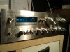
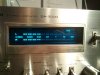
Started the day with collecting the new SA-9800. I must say that it does look rather different than the old one. Wonderful blue VU-meter and an almost scratch free aluminum front.
Later a package arrived with some new parts. I think all is there so when i get time i will start to reassemble the old one and hopefully it will work like it should.

I've cleaned and deoxit the new one. The faceplate and the knobs took a hour to clean (a lot less than the other one) so now they shine just like they should.
Inside there was some dust but almost no rust. No burned components and only one capacitor looked a bit odd (changed) but i think i need to adjust the power boards. The left one is a little hotter than the right but that's not a big thing to sort out. The VU-meter also needs a bit adjusting.
The relay modification is also made in this one. No click at turn of and it takes about 7 seconds until it clicks at start up.

I can't tell you how happy i am now. Just looking puts a big grin on my face. If i listen to it the grin gets even bigger. Sounds so powerful with a lot more detail and a wider sound stage than the CR-2020. The speakers ''disappears'' and you barely notice you are listening through them.

Probably just me being paranoid but does the display take more harm if you have it at bright rather than dim? I have no idea how it works but it would be nice if it would stay this bright and clear in 40 years.

Will post a couple of pictures when i find my phone....
 
As promised, a couple of pictures.

Still working like a charm. I cleaned the relay and that fixed the uneven volume on the VU-meter. I also adjusted everything according to the manual and it took some time but now everything is stable and correct.

The old one is now ready to be tested. I fitted everything and checked it probably 10 times. Hopefully it won't let smoke out but it's always nerve wrecking. DBT on the way!
 

Attachments

  • DSC00298.JPG
    DSC00298.JPG
    188.9 KB · Views: 74
  • DSC00299.JPG
    DSC00299.JPG
    202.1 KB · Views: 68
Started the old one up with a 25w bulb. Did dim a bit but not as much as i would have hoped for. Checked the output and one had 0.5v and the other one had 22v... It's weird since none of the output transistors are shorted.
Any tip or should i just desolder everything and test all of the components individually?
 
Q34 and Q36 are also functional.

There can't be a dead short that's causing the problem since if i unplug it the voltage drops to 0, even when the rail voltages are still 22/-22v.
 
Back
Top Bottom