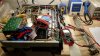
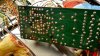
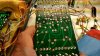
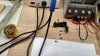
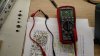
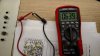
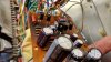
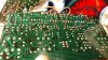
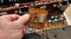
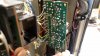
My receiver developed some issues in the right channel and was cutting out. Yesterday I popped the cover and checked out the power supply board and saw a pretty burnt board so I get to rebuild this unit. Sweet, I am excited!
Voltage Right Side -0.010v
Current Idle Right Side 20mv
Voltage Left Side -0.038v
Current Idle Left Side 31mv
If I am understanding correctly with the bleed resistor on these large caps I should not have to be concerned about them still having a charge. When I rebuilt my Kenwood I used a 3w resistor as a bleed resistor and never had issues. Should I do trim pots and relay since it does not sound like those have issues?
Am I missing anything from all the threads on this receiver?
Thanks!
Notes to check
black dmm lead to a bare metal chassis ground
probe with (TIP INSULATED) red probe:
awr-054 power supply board:
pin 14 +56v
pin 15 +24v
pin 13 +35v
pin 10 -56v
pin 11 -24v
pin 9 -13v
pin 8 +13v
THEN, these NEXT readings are different, the black lead is removed from ground and goes on one of the two leads of the named resistor, with the red lead going on the OTHER lead of THAT resistor. If your meter doesn't automatically switch to a lower voltage range for small voltages, you will have to - I expect you to read at or under a volt.
Read the voltage across R11 (follow the foil back from pin 14) brown black black gold color code
Read the voltage across R12 (follow the foil back from pin 10) brown black black gold color code
Read the voltage across R20 (follow the foil back from pin 8) orange orange gold gold color code
Read the voltage across R21 (follow the foil back from pin 13) brown black black gold color code
Does this BOM look current?
Relay and Trimmer Pots
Pioneer SX-1010, 939, 838, et.al., Relay Replacement
653-LY2F-DC24 or 653-LY4F-DC24
652-3386H-1-501LF 500ohms 3386H Single Turn 3/8" ? 10% parallel to pcb
SX-1010 idle current adjust
652-3296P-1-202LF 2Kohms 3296P Multi Turn : 12 3/8" Sealed parallel to pcb
SX-1010 offset voltage adjust
Muting Assembly (AWM-039-A)
AWM-039: C1: .47uF 50v CEA: 667-ECQ-V1H474JL .47uF 50v
AWM-039: C2: 47uF 50v CEA: 647-UPW1H470MED 47uF 50v
Equalizer Amp Assembly (AWF-013-0) (Q1 & Q3 and Q2 & Q4 should be gain matched)
AWF-013: C1: 2.2uF 25v CSSA: 647-UKL1H2R2KDDANA 2.2uF 50v
AWF-013: C2: 2.2uF 25v CSSA: 647-UKL1H2R2KDDANA 2.2uF 50v
AWF-013: C5: 470uF 6.3v CEANL: 647-UKL1C471KPD 470uF 16v
AWF-013: C6: 470uF 6.3v CEANL: 647-UKL1C471KPD 470uF 16v
AWF-013: C9: 100uF 6.3v CEANL: 647-UKL1E101KPDANA 100uF 25v
AWF-013: C10: 100uF 6.3v CEANL: 647-UKL1E101KPDANA 100uF 25v
AWF-013: C11: 10uF 10v CEANL: 647-UKL1C100MDDANA 10uF 16v
AWF-013: C12: 10uF 10v CEANL: 647-UKL1C100MDDANA 10uF 16v
AWF-013: C19: 100uF 25v CEANL: 647-UKL1E101KPDANA 100uF 25v
AWF-013: C20: 100uF 25v CEANL: 647-UKL1E101KPDANA 100uF 25v
AWF-013: C21: 220uF 16v CEANL: 647-UKL1C221KPDANA 220uF 16v
AWF-013: Q1: 2SA725: 512-KSA992FBU
AWF-013: Q2: 2SA725: 512-KSA992FBU
AWF-013: Q3: 2SA725: 512-KSA992FBU
AWF-013: Q4: 2SA725: 512-KSA992FBU
AWF-013: Q5: 2SC1313: 512-KSC1845FTA
AWF-013: Q6: 2SC1313: 512-KSC1845FTA
AWF-013: Q7: 2SC1313: 512-KSC1845FTA
AWF-013: Q8: 2SC1313: 512-KSC1845FTA
Control Amp Assembly (AWG-027) (Checked C49-52, I have 100uF 16v CEA)
AWG-027: C1: .33uF 25v: CSSA: 667-ECQ-V1H334JL .33uF 50v
AWG-027: C2: .33uF 25v: CSSA: 667-ECQ-V1H334JL .33uF 50v
AWG-027: C7: 100uF 10v CEA: 667-EEU-FM1E101 100uF 25v
AWG-027: C8: 100uF 10v CEA: 667-EEU-FM1E101 100uF 25v
AWG-027: C13: 2.2uF 25v CSSA: 647-UKL1H2R2KDDANA 2.2uF 50v
AWG-027: C14: 2.2uF 25v CSSA: 647-UKL1H2R2KDDANA 2.2uF 50v
AWG-027: C15: 4.7uF 50v CEA: 667-EEU-FC1H4R7 4.7uF 50v
AWG-027: C16: 4.7uF 50v CEA: 667-EEU-FC1H4R7 4.7uF 50v
AWG-027: C23: 4.7uF 25v CEANL: 647-UKL1H4R7KDDANA 4.7uF 50v
AWG-027: C24: 4.7uF 25v CEANL: 647-UKL1H4R7KDDANA 4.7uF 50v
AWG-027: C25: 10uF 16v CEA: 667-EEU-FC1H100L 10uF 50v
AWG-027: C26: 10uF 16v CEA: 667-EEU-FC1H100L 10uF 50v
AWG-027: C29: 100uF 10v CEA: 667-EEU-FM1E101 100uF 25v
AWG-027: C30: 100uF 10v CEA: 667-EEU-FM1E101 100uF 25v
AWG-027: C31: 4.7uF 50v CEA: 667-EEU-FC1H4R7 4.7uF 50v
AWG-027: C32: 4.7uF 50v CEA: 667-EEU-FC1H4R7 4.7uF 50v
AWG-027: C39: 4.7uF 25v CEANL: 647-UKL1H4R7KDDANA 4.7uF 50v
AWG-027: C40: 4.7uF 25v CEANL: 647-UKL1H4R7KDDANA 4.7uF 50v
AWG-027: C41: 10uF 16v CEA: 667-EEU-FC1H100L 10uF 50v
AWG-027: C42: 10uF 16v CEA: 667-EEU-FC1H100L 10uF 50v
AWG-027: C45: 100uF 10v CEA: 667-EEU-FM1E101 100uF 25v
AWG-027: C46: 100uF 10v CEA: 667-EEU-FM1E101 100uF 25v
AWG-027: C47: 2.2uF 25v CSSA: 647-UKL1H2R2KDDANA 2.2uF 50v
AWG-027: C48: 2.2uF 25v CSSA: 647-UKL1H2R2KDDANA 2.2uF 50v
AWG-027: C49: 47uF 16v CEA or 100uF 16v CEA: 667-EEU-FM1E101 100uF 25v or 667-EEU-FM1E470 47uF 25v
AWG-027: C50: 47uF 16v CEA or 100uF 16v CEA: 667-EEU-FM1E101 100uF 25v or 667-EEU-FM1E470 47uF 25v
AWG-027: C51: 47uF 16v CEA or 100uF 16v CEA: 667-EEU-FM1E101 100uF 25v or 667-EEU-FM1E470 47uF 25v
AWG-027: C52: 47uF 16v CEA or 100uF 16v CEA: 667-EEU-FM1E101 100uF 25v or 667-EEU-FM1E470 47uF 25v
AWG-027: Q1: 2SA725: 512-KSA992FBU
AWG-027: Q2: 2SA725: 512-KSA992FBU
AWG-027: Q3: 2SC1313: 512-KSC1845FTA
AWG-027: Q4: 2SC1313: 512-KSC1845FTA
AWG-027: Q5: 2SC1313: 512-KSC1845FTA
AWG-027: Q6: 2SC1313: 512-KSC1845FTA
AWG-027: Q7: 2SC1313: 512-KSC1845FTA
AWG-027: Q8: 2SC1313: 512-KSC1845FTA
Power Amp Assembly (AWH-032-0) (Checked I do have the 1.5uF cap.)
(Q1 and Q2 should be gain matched) How can I accomplish this?
AWH-032: C1: .68uF 25v CSSA: 667-ECQ-V1H684JL .68uF 50v
AWH-032: C2: 1.5uF 25v CSSA: 647-UKL1H1R5MDD1TA 1.5uF 50v
AWH-032: C4: 10uF 16v CEA: 647-UPW1E100MDD 10uF 25v
AWH-032: C8: 330uF 6.3v CEA: 647-UPW1A331MPD 330uF 10v
AWH-032: Q1: 2SA726: 512-KSA992FBU
AWH-032: Q2: 2SA726: 512-KSA992FBU
AWH-032: Q3: 2SA726: 512-KSA992FBU
AWH-032: Q5: 2SC1451: 512-KSC3503DSTU
AWH-032: Q6: 2SC1451: 512-KSC3503DSTU
Protection Assembly (AWM-062-0)
AWM-062: C1: .22uF 10v CSSA: 667-ECQ-V1H224JL2 .22uF 50v
AWM-062: C2: .22uF 10v CSSA: 667-ECQ-V1H224JL2 .22uF 50v
AWM-062: C3: 330uF 6.3v CEA: 647-UPW1A331MPD 330uF 10v
AWM-062: C4: 330uF 6.3v CEA: 647-UPW1A331MPD 330uF 10v
AWM-062: C5: 4.7uF 25v CEA: 647-UPW1V4R7MDD 4.7uF 35v
AWM-062: C6: 100uF 16v CEA: 647-UPW1E101MED 100uF 25v
AWM-062: Q1: 2SC869: 512-KSC1845FTA
AWM-062: Q2: 2SC869: 512-KSC1845FTA
AWM-062: Q6: 2SC945: 512-KSC2383YTA
AWM-062: Q7: 2SC1384: 512-KSC2690AYS
1N4004 flyback diode is added between pins 9 (anode +) and 10 (cathode -)
Power Supply Assembly (AWR-054-0) (Resistors are optional but recommended, stand them up off the board about a half inch when mounting the new ones)
AWR-054: C8: 470uF 80v CEA: 647-UPW2A471MHD 470uF 100v
AWR-054: C9: 470uF 80v CEA: 647-UPW2A471MHD 470uF 100v
AWR-054: C10: 100uF 63v CEA: 647-UPW2A101MHD 100uF 100v
AWR-054: C11: 100uF 63v CEA: 647-UPW2A101MHD 100uF 100v
AWR-054: C12: 100uF 35v CEA: 647-UPW1H101MPD 100uF 50v
AWR-054: C13: 100uF 35v CEA: 647-UPW1H101MPD 100uF 50v
AWR-054: C14: 47uF 50v CEA: 647-UPW1J470MPD 47uF 63v
AWR-054: C18: 1000uF 35v CEA: 647-UPW1H102MHD 1000uF 50v
AWR-054: C19: 220uF 16v CEA: 647-UPW1V221MPD6 220uF 35v
AWR-054: C20: 2200uF 10v CEA: 647-UPW1C222MHD 2200uF 16v
AWR-054: C21: 2200uF 10v CEA: 647-UPW1C222MHD 2200uF 16v
AWR-054: R11: 10 Ohm 1/4 watt: 660-MFS1/2DCT52R10R0 10 Ohm 1/2 watt
AWR-054: R12: 10 Ohm 1/4 watt: 660-MFS1/2DCT52R10R0 10 Ohm 1/2 watt
AWR-054: R20: 3.3 Ohm 1/4 watt: 660-MF1/2DCT52R3R32F 3.32 Ohm 1/2 watt
AWR-054: R21: 10 Ohm 1/4 watt: 660-MFS1/2DCT52R10R0 10 Ohm 1/2 watt
AWR-054: Q1: 2SD313: 863-MJE15032G
AWR-054: Q2: 2SC869: 512-KSC2383YBU
AWR-054: Q3: 2SC869: 512-KSC2383YBU
AWR-054: Q4: 2SB507: 863-MJE15033G
AWR-054: Q5: 2SA628A: 512-KSA1013YBU
AWR-054: Q6: 2SA628A: 512-KSA1013YBU
AWR-054: Q7: 2SD313: 863-MJE15032G
AWR-054: Q8: 2SC1384: 512-KSC2690AYS
Main filter caps, 18000uF 63v, 50mm dia x 90mm high:
(Digi-Key) 565-3331-ND 18000uF 75v screw terminal 50.80mm dia x 79.38mm high
Across Main filter caps
5989-100V2.2-F 2.2uf cornell dublier 100v met poly $1.19 ea or 5989-250V2.2-F 2.2uf cornell dublier 250v met poly $1.75 ea
Random picture for fun
Voltage Right Side -0.010v
Current Idle Right Side 20mv
Voltage Left Side -0.038v
Current Idle Left Side 31mv
If I am understanding correctly with the bleed resistor on these large caps I should not have to be concerned about them still having a charge. When I rebuilt my Kenwood I used a 3w resistor as a bleed resistor and never had issues. Should I do trim pots and relay since it does not sound like those have issues?
Am I missing anything from all the threads on this receiver?
Thanks!
Notes to check
black dmm lead to a bare metal chassis ground
probe with (TIP INSULATED) red probe:
awr-054 power supply board:
pin 14 +56v
pin 15 +24v
pin 13 +35v
pin 10 -56v
pin 11 -24v
pin 9 -13v
pin 8 +13v
THEN, these NEXT readings are different, the black lead is removed from ground and goes on one of the two leads of the named resistor, with the red lead going on the OTHER lead of THAT resistor. If your meter doesn't automatically switch to a lower voltage range for small voltages, you will have to - I expect you to read at or under a volt.
Read the voltage across R11 (follow the foil back from pin 14) brown black black gold color code
Read the voltage across R12 (follow the foil back from pin 10) brown black black gold color code
Read the voltage across R20 (follow the foil back from pin 8) orange orange gold gold color code
Read the voltage across R21 (follow the foil back from pin 13) brown black black gold color code
Does this BOM look current?
Relay and Trimmer Pots
Pioneer SX-1010, 939, 838, et.al., Relay Replacement
653-LY2F-DC24 or 653-LY4F-DC24
652-3386H-1-501LF 500ohms 3386H Single Turn 3/8" ? 10% parallel to pcb
SX-1010 idle current adjust
652-3296P-1-202LF 2Kohms 3296P Multi Turn : 12 3/8" Sealed parallel to pcb
SX-1010 offset voltage adjust
Muting Assembly (AWM-039-A)
AWM-039: C1: .47uF 50v CEA: 667-ECQ-V1H474JL .47uF 50v
AWM-039: C2: 47uF 50v CEA: 647-UPW1H470MED 47uF 50v
Equalizer Amp Assembly (AWF-013-0) (Q1 & Q3 and Q2 & Q4 should be gain matched)
AWF-013: C1: 2.2uF 25v CSSA: 647-UKL1H2R2KDDANA 2.2uF 50v
AWF-013: C2: 2.2uF 25v CSSA: 647-UKL1H2R2KDDANA 2.2uF 50v
AWF-013: C5: 470uF 6.3v CEANL: 647-UKL1C471KPD 470uF 16v
AWF-013: C6: 470uF 6.3v CEANL: 647-UKL1C471KPD 470uF 16v
AWF-013: C9: 100uF 6.3v CEANL: 647-UKL1E101KPDANA 100uF 25v
AWF-013: C10: 100uF 6.3v CEANL: 647-UKL1E101KPDANA 100uF 25v
AWF-013: C11: 10uF 10v CEANL: 647-UKL1C100MDDANA 10uF 16v
AWF-013: C12: 10uF 10v CEANL: 647-UKL1C100MDDANA 10uF 16v
AWF-013: C19: 100uF 25v CEANL: 647-UKL1E101KPDANA 100uF 25v
AWF-013: C20: 100uF 25v CEANL: 647-UKL1E101KPDANA 100uF 25v
AWF-013: C21: 220uF 16v CEANL: 647-UKL1C221KPDANA 220uF 16v
AWF-013: Q1: 2SA725: 512-KSA992FBU
AWF-013: Q2: 2SA725: 512-KSA992FBU
AWF-013: Q3: 2SA725: 512-KSA992FBU
AWF-013: Q4: 2SA725: 512-KSA992FBU
AWF-013: Q5: 2SC1313: 512-KSC1845FTA
AWF-013: Q6: 2SC1313: 512-KSC1845FTA
AWF-013: Q7: 2SC1313: 512-KSC1845FTA
AWF-013: Q8: 2SC1313: 512-KSC1845FTA
Control Amp Assembly (AWG-027) (Checked C49-52, I have 100uF 16v CEA)
AWG-027: C1: .33uF 25v: CSSA: 667-ECQ-V1H334JL .33uF 50v
AWG-027: C2: .33uF 25v: CSSA: 667-ECQ-V1H334JL .33uF 50v
AWG-027: C7: 100uF 10v CEA: 667-EEU-FM1E101 100uF 25v
AWG-027: C8: 100uF 10v CEA: 667-EEU-FM1E101 100uF 25v
AWG-027: C13: 2.2uF 25v CSSA: 647-UKL1H2R2KDDANA 2.2uF 50v
AWG-027: C14: 2.2uF 25v CSSA: 647-UKL1H2R2KDDANA 2.2uF 50v
AWG-027: C15: 4.7uF 50v CEA: 667-EEU-FC1H4R7 4.7uF 50v
AWG-027: C16: 4.7uF 50v CEA: 667-EEU-FC1H4R7 4.7uF 50v
AWG-027: C23: 4.7uF 25v CEANL: 647-UKL1H4R7KDDANA 4.7uF 50v
AWG-027: C24: 4.7uF 25v CEANL: 647-UKL1H4R7KDDANA 4.7uF 50v
AWG-027: C25: 10uF 16v CEA: 667-EEU-FC1H100L 10uF 50v
AWG-027: C26: 10uF 16v CEA: 667-EEU-FC1H100L 10uF 50v
AWG-027: C29: 100uF 10v CEA: 667-EEU-FM1E101 100uF 25v
AWG-027: C30: 100uF 10v CEA: 667-EEU-FM1E101 100uF 25v
AWG-027: C31: 4.7uF 50v CEA: 667-EEU-FC1H4R7 4.7uF 50v
AWG-027: C32: 4.7uF 50v CEA: 667-EEU-FC1H4R7 4.7uF 50v
AWG-027: C39: 4.7uF 25v CEANL: 647-UKL1H4R7KDDANA 4.7uF 50v
AWG-027: C40: 4.7uF 25v CEANL: 647-UKL1H4R7KDDANA 4.7uF 50v
AWG-027: C41: 10uF 16v CEA: 667-EEU-FC1H100L 10uF 50v
AWG-027: C42: 10uF 16v CEA: 667-EEU-FC1H100L 10uF 50v
AWG-027: C45: 100uF 10v CEA: 667-EEU-FM1E101 100uF 25v
AWG-027: C46: 100uF 10v CEA: 667-EEU-FM1E101 100uF 25v
AWG-027: C47: 2.2uF 25v CSSA: 647-UKL1H2R2KDDANA 2.2uF 50v
AWG-027: C48: 2.2uF 25v CSSA: 647-UKL1H2R2KDDANA 2.2uF 50v
AWG-027: C49: 47uF 16v CEA or 100uF 16v CEA: 667-EEU-FM1E101 100uF 25v or 667-EEU-FM1E470 47uF 25v
AWG-027: C50: 47uF 16v CEA or 100uF 16v CEA: 667-EEU-FM1E101 100uF 25v or 667-EEU-FM1E470 47uF 25v
AWG-027: C51: 47uF 16v CEA or 100uF 16v CEA: 667-EEU-FM1E101 100uF 25v or 667-EEU-FM1E470 47uF 25v
AWG-027: C52: 47uF 16v CEA or 100uF 16v CEA: 667-EEU-FM1E101 100uF 25v or 667-EEU-FM1E470 47uF 25v
AWG-027: Q1: 2SA725: 512-KSA992FBU
AWG-027: Q2: 2SA725: 512-KSA992FBU
AWG-027: Q3: 2SC1313: 512-KSC1845FTA
AWG-027: Q4: 2SC1313: 512-KSC1845FTA
AWG-027: Q5: 2SC1313: 512-KSC1845FTA
AWG-027: Q6: 2SC1313: 512-KSC1845FTA
AWG-027: Q7: 2SC1313: 512-KSC1845FTA
AWG-027: Q8: 2SC1313: 512-KSC1845FTA
Power Amp Assembly (AWH-032-0) (Checked I do have the 1.5uF cap.)
(Q1 and Q2 should be gain matched) How can I accomplish this?
AWH-032: C1: .68uF 25v CSSA: 667-ECQ-V1H684JL .68uF 50v
AWH-032: C2: 1.5uF 25v CSSA: 647-UKL1H1R5MDD1TA 1.5uF 50v
AWH-032: C4: 10uF 16v CEA: 647-UPW1E100MDD 10uF 25v
AWH-032: C8: 330uF 6.3v CEA: 647-UPW1A331MPD 330uF 10v
AWH-032: Q1: 2SA726: 512-KSA992FBU
AWH-032: Q2: 2SA726: 512-KSA992FBU
AWH-032: Q3: 2SA726: 512-KSA992FBU
AWH-032: Q5: 2SC1451: 512-KSC3503DSTU
AWH-032: Q6: 2SC1451: 512-KSC3503DSTU
Protection Assembly (AWM-062-0)
AWM-062: C1: .22uF 10v CSSA: 667-ECQ-V1H224JL2 .22uF 50v
AWM-062: C2: .22uF 10v CSSA: 667-ECQ-V1H224JL2 .22uF 50v
AWM-062: C3: 330uF 6.3v CEA: 647-UPW1A331MPD 330uF 10v
AWM-062: C4: 330uF 6.3v CEA: 647-UPW1A331MPD 330uF 10v
AWM-062: C5: 4.7uF 25v CEA: 647-UPW1V4R7MDD 4.7uF 35v
AWM-062: C6: 100uF 16v CEA: 647-UPW1E101MED 100uF 25v
AWM-062: Q1: 2SC869: 512-KSC1845FTA
AWM-062: Q2: 2SC869: 512-KSC1845FTA
AWM-062: Q6: 2SC945: 512-KSC2383YTA
AWM-062: Q7: 2SC1384: 512-KSC2690AYS
1N4004 flyback diode is added between pins 9 (anode +) and 10 (cathode -)
Power Supply Assembly (AWR-054-0) (Resistors are optional but recommended, stand them up off the board about a half inch when mounting the new ones)
AWR-054: C8: 470uF 80v CEA: 647-UPW2A471MHD 470uF 100v
AWR-054: C9: 470uF 80v CEA: 647-UPW2A471MHD 470uF 100v
AWR-054: C10: 100uF 63v CEA: 647-UPW2A101MHD 100uF 100v
AWR-054: C11: 100uF 63v CEA: 647-UPW2A101MHD 100uF 100v
AWR-054: C12: 100uF 35v CEA: 647-UPW1H101MPD 100uF 50v
AWR-054: C13: 100uF 35v CEA: 647-UPW1H101MPD 100uF 50v
AWR-054: C14: 47uF 50v CEA: 647-UPW1J470MPD 47uF 63v
AWR-054: C18: 1000uF 35v CEA: 647-UPW1H102MHD 1000uF 50v
AWR-054: C19: 220uF 16v CEA: 647-UPW1V221MPD6 220uF 35v
AWR-054: C20: 2200uF 10v CEA: 647-UPW1C222MHD 2200uF 16v
AWR-054: C21: 2200uF 10v CEA: 647-UPW1C222MHD 2200uF 16v
AWR-054: R11: 10 Ohm 1/4 watt: 660-MFS1/2DCT52R10R0 10 Ohm 1/2 watt
AWR-054: R12: 10 Ohm 1/4 watt: 660-MFS1/2DCT52R10R0 10 Ohm 1/2 watt
AWR-054: R20: 3.3 Ohm 1/4 watt: 660-MF1/2DCT52R3R32F 3.32 Ohm 1/2 watt
AWR-054: R21: 10 Ohm 1/4 watt: 660-MFS1/2DCT52R10R0 10 Ohm 1/2 watt
AWR-054: Q1: 2SD313: 863-MJE15032G
AWR-054: Q2: 2SC869: 512-KSC2383YBU
AWR-054: Q3: 2SC869: 512-KSC2383YBU
AWR-054: Q4: 2SB507: 863-MJE15033G
AWR-054: Q5: 2SA628A: 512-KSA1013YBU
AWR-054: Q6: 2SA628A: 512-KSA1013YBU
AWR-054: Q7: 2SD313: 863-MJE15032G
AWR-054: Q8: 2SC1384: 512-KSC2690AYS
Main filter caps, 18000uF 63v, 50mm dia x 90mm high:
(Digi-Key) 565-3331-ND 18000uF 75v screw terminal 50.80mm dia x 79.38mm high
Across Main filter caps
5989-100V2.2-F 2.2uf cornell dublier 100v met poly $1.19 ea or 5989-250V2.2-F 2.2uf cornell dublier 250v met poly $1.75 ea
Random picture for fun