You are using an out of date browser. It may not display this or other websites correctly.
You should upgrade or use an alternative browser.
You should upgrade or use an alternative browser.
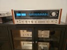
Pioneer SX-1010 refresh
- Thread starter Junfan
- Start date


goat67
Addicted Member
Nice job.
I use the silpads and I put a real light coat of paste on both sides using a safety razor as a spatula. I can't help myself.
Can you provide a part number for these or a better description I would like to include them with my order....
Thanks
Last edited:
Yes, sure. I get those from Digikey just because I have not found them at mouser. I bet they carry them.
Bergquist SPK10-0.006-00-58
http://www.digikey.com/scripts/DkSearch/dksus.dll?Detail&itemSeq=193551006&uq=635952684508477334
Bergquist SPK10-0.006-00-58
http://www.digikey.com/scripts/DkSearch/dksus.dll?Detail&itemSeq=193551006&uq=635952684508477334
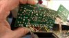
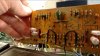

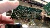
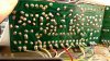
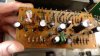

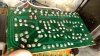
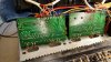
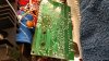
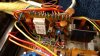

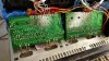


"1N4004 flyback diode is added between pins 9 (anode) and 10 (cathode)"
Quote MTF:
When the relay current is turned off, there is a watt of magnetic field in the relay coil that collapses. This causes a negative voltage spike (-60v or so!!) across the relay coil, which does not make the transistor happy. The diode prevents this voltage from going below -0.6v or so, protecting the relay drive transistor. Pioneer did it on later, more expensive models, and increases the longevity of the relay drive transistor. I, of course, specified a much more robust transistor for that position.


I know this is an older post, but purchased a 1010 recently. I plan on going through it soon. I noticed the post says between pins 9 and 10, but the picture shows the diode on 9 and 11. Is that where it actually goes?
"1N4004 flyback diode is added between pins 9 (anode) and 10 (cathode)"
Quote MTF:
When the relay current is turned off, there is a watt of magnetic field in the relay coil that collapses. This causes a negative voltage spike (-60v or so!!) across the relay coil, which does not make the transistor happy. The diode prevents this voltage from going below -0.6v or so, protecting the relay drive transistor. Pioneer did it on later, more expensive models, and increases the longevity of the relay drive transistor. I, of course, specified a much more robust transistor for that position.

If you look at the back side of the board, pins 10 & 11 are tied together, so really it doesn't matter which pin (10 or 11) gets the cathode end of the diode. See manual page below. 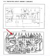
Thank you sir. Worked in electronics most of my life. Security and access control systems. Started getting into vintage audio and am now slightly obsessed. Really want to get into servicing equipment, but didn't plan on starting on the 1010. I have a Pioneer TX-6800 and SA-6800. Think I'm going to start with the tuner and see how that goes. It's inexpensive and can find another if something goes wrong.If you look at the back side of the board, pins 10 & 11 are tied together, so really it doesn't matter which pin (10 or 11) gets the cathode end of the diode. See manual page below. View attachment 3339800