• The move to the new server is done. There are some software and database maintenance updates in process. This has us passing the hat around to help out. We appreciate any donations. Seriously, even a dollar helps. The payment page may be found here - https://www.audiokarma.org/support.html

Pioneer SX-1250 recap and restoration thread!

hi gang,
i noticed that the parts list for the power amp board (awh-048a) only shows replacements for transistors q1 and q2. While i have these out, i would like to replace all the transistors and diodes. Does anyone have a parts list of recommended replaces for the other transistors and the diodes?
Thanks team,
jerry


awh-048 amp quantity shows for both left and right cards
4 q1,q2 2sa750e 512-ksa992fbu hfe gain match 1+ 2

4 q3,q4 2sc1439b 512-ksc3503dstu
4 q5,q6 2sa858b 512-ksa1381estu

2 q7 2sc1904ab 512-ksc3503dstu
2 q8 2sa899ab 512-ksa1381estu
2 q9 2sd610r 512-ksc2073tu
2 q10 2sb630r 512-ksa940tu
2 q11 2sc869c 512-ksc2310ybu
 
Q11 replacement

Thanks for the list.
I was wondering if Q11 (2sc869) could be replaced with a ksc2383 in this circuit. I noticed that on one of the other boards this transistor was used as a sub.
Thanks, Jerry
 
Use with Adcoms

Ok, next questions:
1) For those who used the Adcoms, what did you find was the best way to enlarge the connector wire and bracket hope size without ripping apart your wiring. Figured I would as incase there is an easy way to do this
2) for these large caps, when looking at the front of the receiver, does the negative terminals face forward or backwards. Since this is very important thought I would confirm.

Interesting note when doing the mod on the power supply board, I found heat damage from conductive glue on bottom of a couple caps. I did not glue mine down but am interested what others use to secure larger caps.
 
Q7 part number ?

Hi,
I am changing out the transistors from the above parts list and noticed a possible problem in the following:
q7 2sc1904ab 512-ksc3503dstu
q8 2sa899ab 512-ksa1381estu

I measured the gain of the two parts as I was putting them in and noticed that one had a gain around 80 (ksc3503dstu) and 150 (ksa1381estu).

It looks like from the schematic that q7 and q8 should have the same gain. The original parts were about 150, so think q7 should be ksc3503estu instead of dstu. Please correct me if I am wrong. Thanks.
 
what mouser carries:

512-KSA1381ESTU
512-KSA1381ES End of Life

512-KSC3503DS
512-KSC3503DSTU
512-KSC3503CS End of Life

The TU variant is just shipped in a tube instead of in bulk.

Q7 and Q8 are NOT part of a differential pair. Transistor gain in the q7 and q8 positions (mainly) only affects the loading on the previous stage, these are current drive stages.
 
rolleiman asked: "For those who used the Adcoms, what did you find was the best way to enlarge the connector wire and bracket hope size without ripping apart your wiring"

I used a round jewellers file to open up the contact rings for the large Adcoms on my SX-1050, they are the same ones as used on the SX-1250.

Before I removed the old caps, I wrote the polarity on the chassis next to the caps using a parking pen as a reminder. The new Adcom caps are clearly marked and fit the mounting brackets perfectly. Rubbing alcohol will remove the pen marks when you are done, if it matters to you.
 
take PAPER notes, of wire colors and positions. Photos whenever possible.
 
Polarity and capacitor glue.

- Well I learned another valuable lesson. Mark the chassis with large cap polarity, which I did not. The ones I took out have a black dot on one of the terminals. The cap says Negative Black, so can I assume this it the negative terminal?
From what I remember, the caps were all oriented with the negative terminal facing toward the front of the receiver. Is this what you guys have?

- when I removed caps from the boards, I noticed three instances were the glue holding three of the medium sized caps in place had dried up and started to become conductive and generated heat. I did not glue any of the caps in place. What glue or other material would you recommend using to mechanically dampen the vibration in the caps? Note also that I actually was surprised to find this conductive glue in my Oppo DVD player that was starting to create a heat problem between terminals of a power supply cap!
 
I've never used glue when replacing caps, large or small...Also yes, the black dot on one of the terminals of the filter caps does indicate negative....
 
<snip>
- when I removed caps from the boards, I noticed three instances were the glue holding three of the medium sized caps in place had dried up and started to become conductive and generated heat. I did not glue any of the caps in place. What glue or other material would you recommend using to mechanically dampen the vibration in the caps? Note also that I actually was surprised to find this conductive glue in my Oppo DVD player that was starting to create a heat problem between terminals of a power supply cap!

no glue, glue was for large caps in the factory manufacturing environment, otherwise the big caps would fall off/away from the stuffed board before wave soldering, glue is / was purely a factory requirement.

Pioneer's glue has proved to be pretty inert over the years. Heat does make it more brittle, but that was usually an indication of a generally hot environment inside the chassis - poor ventilation by the owner.

Other manufactures used different glues that proved otherwise, usually not as much conductive as corrosive, eating away component leads.


as for polarity, the 1250 has 4 main caps, and I don't have the afternoon required to dig the 1250 out of the place it is in and look at the bottom for the wire colors, so you will need to use the ohmmeter method to determine the polarity of your cap connections. The power output transistors are TO-3 round cased transistors with the case being the collector.

DO NOT ASSUME THAT THE LEFT SIDE CAPACITOR ALIGNMENTS ARE THE SAME AS THE RIGHT SIDE CAPACITOR ALIGNMENTS!!!!!!!!!!!!!!!!!
check to be correct...


The PNP (2saxxx,2sbxxx or MJ21193G with the arrow pointing INTO the base in the symbol!!) power output transistors case is the collector for the NEGATIVE power, thus it is connected to that capacitor's negative lead, and that capacitors positive lead is connected to ground. (in the center of the two caps)


and the NPN (2scxxx,2sdxxx or MJ21194G with the arrow pointing AWAY FROM the base in the symbol!!) power output transistors case is the collector for the POSITIVE power, thus it is connected to that capacitor's positive lead, and that capacitors negative lead is connected to ground. (in the center of the two caps)

SO...
connect one of your ohmmeter's test leads to the unknown polarity wire that is to be connected to the big capacitor's terminals - the wires are short, so they can only go to one place, - then touch the ohmmeter's OTHER lead one at a time to each of the power transistors case's and when you find a continuity, look at the lettering on that transistor.

if the transistor number is a 2saxxx,2sbxxx or MJ21193G it is a PNP and that is a NEGATIVE voltage going to a negative capacitor terminal

if the transistor number is a 2scxxx,2sdxxx or MJ21194G it is a NPN and that is a POSITIVE voltage going to a positive capacitor terminal

 
Last edited:
Polarity and Burn

Thanks for the info on the polarity.
Mods are coming along slowly but surely.
I got most of my componants changed and down to the last few transistors and broke the glass tube in my pace desolder station. Not sure where to find another tube. Guess I will have to do it the old fasion way. :D
Also have to find some epoxy to glue down a pad I lifted off the PC board. As these are so well built, I was suprised that I did this.
You sure can tell us Rookies!
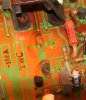
Attached are a couple photos of the burn mark on my board. Perhaps it is not the glue. If it were, I would have suspected the burn to occur between the two terminals and not just one. Interesting. . .
 

Attachments

  • Burn 1.jpg
    Burn 1.jpg
    82.9 KB · Views: 223
  • Burn 2.jpg
    Burn 2.jpg
    74.8 KB · Views: 207
gotta see the pace hand piece to tell if it is a xx03 or xx09 flint glass tube.

www.pacedirect.com
orders@pacedirect.com
301-490-9860


Description:Glass Chamber, Item #: , Product Code: 1265-0009-P1
Unit price:$11.00 USD
Qty:1
Amount:$11.00 USD


The tubes sometimes have a few thousandths smaller diameter hole at the end, trapping large solder blobs - which then have to be melted out.
 
Hi Mark,
I have included photos of the Pace PPS-5 and the handset.
Hope I am not hi-jacking the SX-1250 discussion. . .
 

Attachments

  • Photo 1.jpg
    Photo 1.jpg
    63.5 KB · Views: 148
  • Pace PPS-5.jpg
    Pace PPS-5.jpg
    75.4 KB · Views: 142
hmmm.... 120v iron heater, the 0009 is a good gamble. get yourself some seals front and rear as well as both filter types while you are at it. These are old and the parts are disappearing, f\so get them while the getting's good....
and by now you deserve your own thread.

copy the pertinent stuff from this thread into your new one for continuity.
 
Well, I have changed most of the electrolytics and transistors in the unit and am looking for advise on powering it up and making the proper voltage adjustments.
What is the advantage of bringing it up on a dim bulb tester as opposed to the Variac?
Thanks,
Jerry
 
PLEASE, a new thread!!! dim bulb saves your output transistors if there is a problem.

rolleiman vs. rolleiman59 .... loose your login??? :D
 
Halfway done on my 1250 restoration, next to do is the flat amp, equalizer amp, and associated boards at the front panel. All the power amps, power supply, protection ckt, and stabilizer boards are done and tested. Can't wait to get her done and running...
 
Back
Top Bottom