• The move to the new server is done. There are some software and database maintenance updates in process. This has us passing the hat around to help out. We appreciate any donations. Seriously, even a dollar helps. The payment page may be found here - https://www.audiokarma.org/support.html

Pioneer SX-1250

i got the parts on the way from mouser for AWR-106 board, all i'm worried about is changing the transistors.

no sweat, some are hard to put in backwards, although a few must be insulated from their mounts.

some of them are 1:1 replacement and one or two are different lead arrangements.

you will notice that I included the original and replacement lead layouts for each transistor.

There are of course three leads per transistor, and each has a unique and non-interchangeable function.
 
you need to read ALL of this thread:
http://www.audiokarma.org/forums/showthread.php?t=43186

the arrow is always the emitter, pointing IN is PNP, out is NPN.

has this info also:
attachment.php
 
Last edited:
ok, thanks a lot i will. care if i save the pic above? i just re-read the post #89 with original and replacement parts and #'s and i feel more confident about replacing the transistors now.
 
i just tested the diodes and d3 on awr-106 board has a constant beep. which is connected to that burnt resistor. once i get the resistor replaced i'll test it again just to see if it is bad or not.
 
Not unexpected.

Now, the thing is that C6 could be short circuited, and giving a false reading on D3.

That's why I specify all parts for a complete rebuild, the $ difference is very small, while going piecemeal in fixing it can be an exercise in frustration. Plus stressed parts during the failure could let go later on, adding to the frustration.

This way is a completely fresh deck of cards.
 
Great to see another SX-1250 being given a new lease on life, and glad that the piece hasn't been given up on. There is a real learning curve to becoming able to fix gear, but it is a path that anyone can travel, if they're willing to keep going and keep learning. It ends up being very satisfying, even well before you become expert (I know I'm not there yet! :no:), because you'll have intermediate successes and regular insights along the way.

I love threads like this. Most of what I learned about practical, hands-on gear repair was learned from threads just like this one (supported by theoretical learning from electronics books and online courses and stuff), where one (or more) of the generous uber-techs here walk a novice through the correct procedures. If you search the archives, there are enough repair threads covering different aspects of common models like the 9090s and SX-1250s, as to almost constitute a complete how-to-repair manuals. This thread is adding pages to the latter one.

Such threads have no doubt saved me countless hours of frustration going down blind alleys and probable errors; by reading them, I was prepared and knew how to do things right the first time. "Ditto" for threads on restoring some speakers, like ARs. This kind of information is invaluable.

Every time an "online repair" job is carried out and recorded in a thread like this, it becomes a guide not just for the person whose gear is getting fixed, but for everyone else who reads the thread. Just one of the benefits of AK. Please keep it up! :thmbsp:
 
mark, have you ever tried using a real small flat head screwdriver on the switch's metal casing to spread the case open to deoxitize them? don't worry the case will close back together as long as you don't use too big a flat head screwdriver. i will post a pic afterwhile to show you what i am talking about, but you gotta be very careful not to push it in too far or you could damage something in the switches like tone, tape monitor or loudness (not the push button switches). it makes getting to the contacts with dn5 and faderlube a lot easier.
 
Last edited:
way ahead of you... I polish the contacts.

AFTER first removing the switch from the board, and I am quite adept at all of it. EVEN the pushbutton switches INCLUDING the gang-interlocked function switches.

The last image is the push button type with the staked on top, that cannot be disassembled further.

I have a multitude of specially designed tools including tiny plastic tubes that I can insert into the cracks of those push button switches from the front OR through the small square holes on top and discharge the D-5 at the back of the body of the switch. There isn't a straight shot for a hypodermic needle (of which I also have plenty - blunted tips don't need prescriptions to be lawful in most areas) from the front - I tried... thus the (VERY!!) small plastic tubes

BUT DON'T TAKE THIS AS A CHALLENGE!!!

I only shoot deoxit on repairs, when doing restorations it is a complete disassembly and polishing of switch contacts, with verification of sub 1 ohm contact resistance using the kelvin 4 wire probe method.

attachment.php


attachment.php


attachment.php


attachment.php
 
Last edited:
some people may find it more comfortable to do it like i was talking about instead of unsoldering all those joints. you are a tech with lots of experience in taking that stuff apart. nice pics too. i did it my way and it done a good job, no static anymore on the sx-780, still gotta do the 1250, cleaned it once already and had no static that i know of, but the am, fm, phono 1 and 2 and aux buttons made a popping sound when i pushed them, but the tape monitors and other switches like that were static free. once i get more experienced i will do it your way too.
 
spraying in from the front with a straw or butting the end of the straw up to a square hole on the top of the switch will do just fine, prying is dangerous, and you have to temper your impulse to give risky advice to others with the knowledge that somebody somewhere is gonna try it and bust something and come back here crying or raging in anger.

once you get the spray stream in there, it goes everywhere.

I watch stuff bubbling up through ALL the holes on the top of the push buttons routinely - my extraordinary efforts are more a deoxit conservation effort to keep more if it on the contacts and less of it in the rag.

resistance to cleaning is just that some areas are REALLY bad after 20 to 30 years, requiring multiple treatments. and the result is a clean streak in a sea of blackened corroded metal. Then when the unit is shipped back, the contact can be jarred off the clean streak and we're back to square 0. Thus I like to SEE clean metal all over and KNOW after it ships it will meet the same tests I did before shipping it.
 
ok, got my parts in for awr-106, went ahead and replaced r6 8.2k 1/4 w resistor, but before i soldered the new one in i tested it and it gave the reading of 8k ohms, so i tested the old resistor and got 9k ohm, unsoldered one side of d3, tested and it's still a constant beep. guess i'll replace it next. what could cause a diode to go bad?

i replaced d3 and am getting 839 soldered into the board. i guess i will replace the caps now and the pots
 
Last edited:
How's it going.

Remember, no power unless it's plugged into the Dim Bulb Tester.

The transistors that are mounted with a screw (TO-220, big square with metal tab and a hole in the tab) are insulated from the metal they are mounted on. Mica insulator and white thermal transfer goop. Ohmmeter test before power on, this is raw dc and has great potential for fireworks!!

mount those transistors, press them into place with a little smooshing around to get good thermal contact, then firmly screw them on, finally THEN solder the leads to the board.

we should talk a bit before applying power. about what's next.

btw - mounting transistors, go by the diagram symbol ON the board and the published lead layout. lead layout is usually lettering facing you, leads pointing down, then left to right with the letters.
 
Last edited:
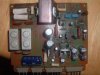
got everything on the board had some probs with some lead spots on board coming off, so i connected it to another on the same line, kinda halfway afraid to even put power to it. i turned both pots all the way counter-clockwise before even installing them. if i need to know anything else let me know.
 
do you want me to post a pic that way you can see if the unmounted transistors are put in right?

here's a pic of it after i got done.


DSCF0948.jpg

the soldering looks like crap because of my cheapo advance auto soldering iron i got for $5 few years ago, got a lil better 1 on the way.
DSCF0949.jpg
 
Last edited:
In this case the pots can be centered. ccw on THESE voltage regulator pots results in the highest voltage, cw is the lowest.

re: lifted foils, carefully smooth them back to where they came from, and bend the component lead down along them, to the next solder joint. Carefully scrape the green stuff off and then solder the length between the two points being careful no t to short to anything else.

Pictures won't hurt, if they are clear.

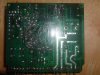
Photograph and post the back side too, to see the repairs, although I'm about toast right now and unfortunately starting the "usual weekend blackout, chores and company over".. others will chime in, and I'll try to drop in, but 1/2 hour long investigative sessions on the pictures are off until sun nite.
 
Back
Top Bottom