• The move to the new server is done. There are some software and database maintenance updates in process. This has us passing the hat around to help out. We appreciate any donations. Seriously, even a dollar helps. The payment page may be found here - https://www.audiokarma.org/support.html

Pioneer SX-440 bias set

calman46

AK Subscriber
Subscriber
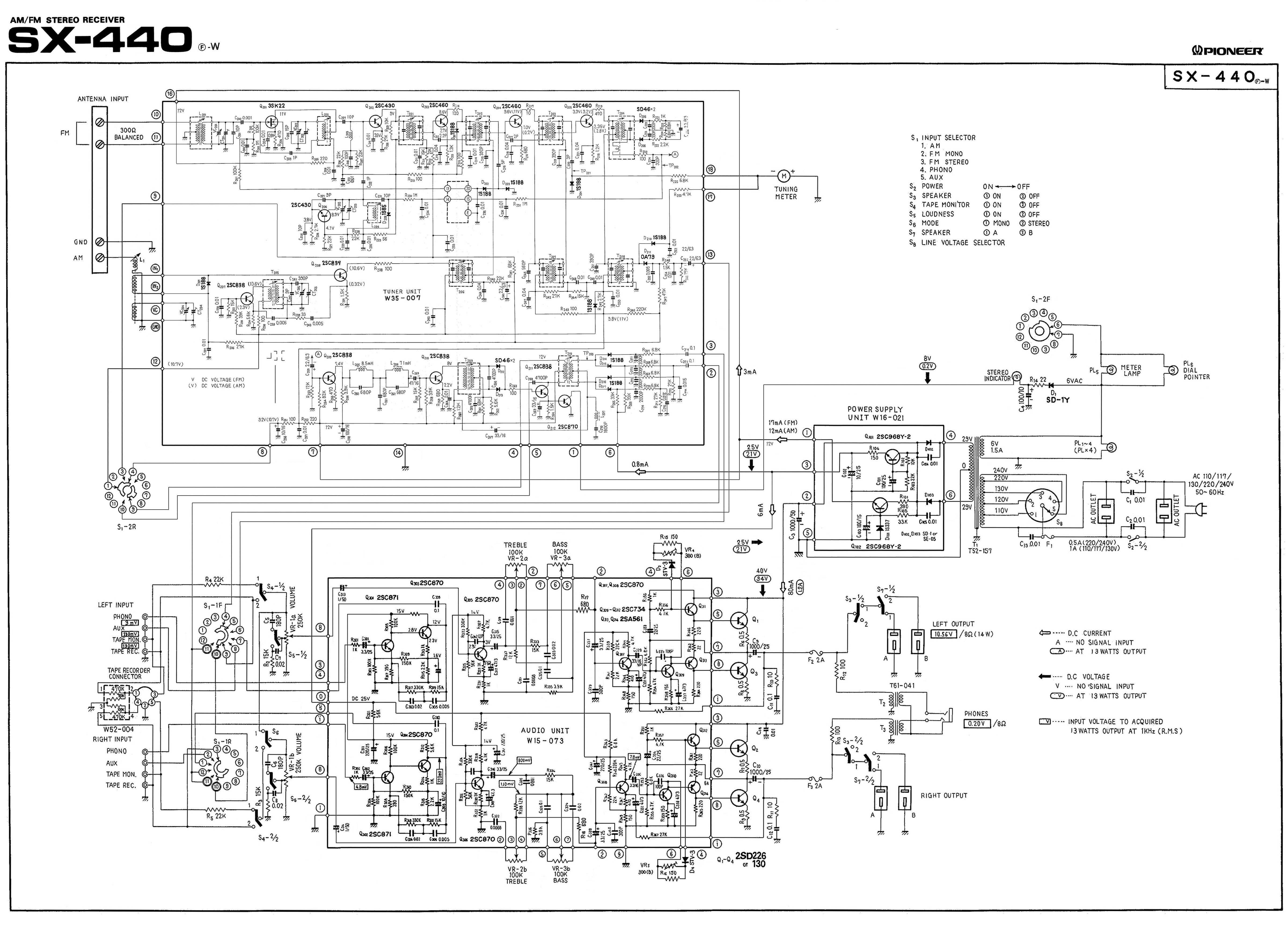
I recapped and upgrade transistors and replace trimmers on the SX-440 I have. The schematic has 80mA to Q1 so I set the new trimmers to 40mV across the emitter resistor . I did 80mA x 0.5 ohms =40mV . The original bias setting were 59mV , 42mV so I went with 40mV for both sides .The SX 440 plays well but seems to be running hot. I have connected to a pair of Sansui SP3500 which are easy drive. Do these SX 440 run hot ? Thanks
upload_2020-8-17_8-7-3.png
 
Register to hide this ad
That indicates 80mA total from the 40V supply. That would indicate 20mA per device since that supply feed both channels. If the voltage drop measurement is being done on a single ½Ω emitter resistor, with NO speakers connected, the voltage drop should be around 20mV. Is that what you are measuring?
 
Why don´t you measure with an amperemeter by temporarily using the meter instead of F2 / F3? Each should measure 40 mA. But: Watthour is right.
 
Some amp designs (output transistors) have a switching threshold and propagation delay requiring that kind of idle current. It's not inordinate, but it does add some heat. To be fully reassured, it might be a good idea to clean the outputs and heat sinks, and refresh the thermal paste for best heat transfer.
 
Bias set to 20mV . I have another question . I'm getting a slight hum in speakers ,its not effective by the volume control .Is this normal for this design? I can hear the transformer hum also. It plays fine and sound pretty good . Thanks
 
You recapped it, so I understand the filter cap also is new and of the proper value. I would take a closer look on the rectifier diodes and perhaps the stabilising circuits for the other stages (I don´t have the schematic of the 440 here).
 
Try increasing the 1000µF main filter by paralleling it with more capacitance to see if that improves the hum (if you already replaced it).
 
Last edited:
EDIT: schematic for LX440A and not SX440

Hello! Can you explain to me how do you calculate the bias on the SX-440 ? I have a LX-440A recapped with the help of @paul_ral but I didn't try to set the bias.

On the schematics, the value of Q1/Q2 is a little different than the SX-440 with 70mA compared to 80mA.

I still have a little hum on my tweeter/medium that I try to fix. I don't know if this setting will fix the hum but I would like to try and understand a little more the working of the bias.
Screenshot 2021-01-01 at 16.47.04.png
 

Attachments

  • Screenshot 2021-01-01 at 16.47.04.png
    Screenshot 2021-01-01 at 16.47.04.png
    354.6 KB · Views: 49
Last edited:
Hello! Can you explain to me how do you calculate the bias on the SX-440 ? I have a LX-440A recapped with the help of @paul_ral but I didn't try to set the bias.

On the schematics, the value of Q1/Q2 is a little different than the SX-440 with 70mA compared to 80mA.

I still have a little hum on my tweeter/medium that I try to fix. I don't know if this setting will fix the hum but I would like to try and understand a little more the working of the bias.
View attachment 2083510
Bias is calculated by measuring the voltage drop across one of the output transistor emitter resistors (R8 left), then applying Ohm's Law: I = Voltage drop / 0.5Ω. Do this for each channel (R9 right). The current in the power supply feed includes bias for both channels, and steady state current for the rest of the power amp circuit as well.
 
EDIT: values for LX440A and not SX440

Thanks @merlynski for your quick answer ! Just to be sure of what I'm going to do, I expose my plan :
- I turn the volume to zero, I turn on the switch of A and B speaker, I disconnect all wires speakers and no RCA on any input.
- I connect my voltmeter between the leg of R8 (it's identified in the picture).
- I set the voltmeter to 200mV.
- 70mA * 0.5Ω = 35mV for both channels so theoretically 17,5mV (35/2) across R8.
- I rotate the trimmer of the channel until having 17,5mV on the voltmeter.
- I do the same on the other channel and resistance.

Am I right or I miss something ?
 

Attachments

  • IMG_7395.jpg
    IMG_7395.jpg
    170 KB · Views: 63
Last edited:
Another beginner's question : is it normal that the voltage value between R8 fluctuates between +/- 1mV when the amp is power on?

For information, the first value for R8 (if I'm right on the measurement) is 4mV.
 
Last edited:
Voltage measured there should be relatively stable. Be certain that there is no audio signal input to the amp board. Select an unused input (Tape Mon, etc.) to accomplish this.
 
Voltage should be relatively stable, but 1mV +/- does strike me as excessive. If you are on the 200mV range, you are measuring near the bottom of the meters range, a (possibly) less accurate (and stable) measurement.
You cannot just use half of the power supply line current as your bias goal, because there are other current paths in the power amp that it feeds (bias spreader & driver transistor circuit).
You should have your meter leads clipped across the emitter resistor (R8) to measure bias. The 'ground' connection on this schematic is rather ambiguous.
Have you noticed the pin numbers on the power amp PCB (Audio Unit AWK-008) schematic have a dot or two dots above them in their circles? The number itself is used multiple times, and pins differentiated by the dots above it.
I don't see any spec for the bias for the LX-440A or the SX-440. I have suggested 20mA (from AK observations) as a reasonable bias to start, which would be 10mVdc across one 0.5Ω emitter resistor.
Does adjusting VR4 (for left channel) change the bias voltage across R8?
 
Last edited:
So we're all on the same sheet of music...

PioneerSX-440F-WSchematic.jpg
 
I am unsure. The OP identified the subject unit as the SX. Before the next round of lock-downs, I may look into the LX. The documents posted on HFE look substantially different, with different board assembly P/Ns and more distinctions.
 
Last edited:
I am unsure. The OP identified the subject unit as the SX. Before the next round of lock-downs, I may look into the LX. The documents posted on HFE look substantially different, with different board assembly P/Ns and more distinctions.
The thread OP is calman46 and started the thread with the SX-440. In post 11 a new poster stephane495 asked about his LX-440A:
I have a LX-440A recapped with the help of @paul_ral but I didn't try to set the bias.
I noticed the change, but did not ask new (second) poster to start a new thread. That may have been a mistake on my part. I did download the LX-440A schematic and noted the similarity and differences between them, and continued the thread, as the power amp output stage architectures are similar.
I am still waiting for the answer to my last question posed to stephane495, It is the middle of the night in Europe now.
 
Last edited:
Back
Top Bottom