
• The move to the new server is done. There are some software and database maintenance updates in process. This has us passing the hat around to help out. We appreciate any donations. Seriously, even a dollar helps. The payment page may be found here - https://www.audiokarma.org/support.html

Pioneer SX-440 bias set

Thanks for the speedy reply, @Watthour !

If I measure across the resistor based on the configuration in the picture below I'm getting roughly 2 mV on both of them. I've replaced most all of the caps and transistors on both the PS and "Audio Unit" so I figured it would be off some. I don't have any experience adjusting the bias on this unit, assuming VR 4 and VR 5 will get me up to the proper range? Also, should I be in AUX function with volume at zero, and does the unit need to be warmed up when the adjustment is made?
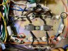
IMG_0321.jpg
 
This is the setting procedure for a sx-770 which is a cap coupled amp like the 440.
The idle current is running at 80mA on your 440.
Sub in the numbers for the 440 and set the amp for that.

MTF's cap coupled setting procedure for a sx-770:

The outputs: set one collector to HALF of the other collector's voltage with VR1(VR2) - easy to hit, it's the output transistor's CASE.
You want to play around, double checking for symmetrical clipping, go ahead, when you are done the result won't be much different than that thumbnail.
We are trying to avoid MAJOR imbalances that would reduce output swing by 50%, not less than 1%.

The scat shows 50mA idle to both main amps. Yours's is 80mA's (+B1)
thus 25mA draw per channel. Yours's will be 40mA's (edit 20mA)

Rather than fool around trying to figure quiescent draw of the rest of the circuit, set each channel to 25 mA which is 0.0125v across one of it's 0.5 ohm resistors using VR3(VR4).

For your 440:
E = I x R
E = 0.020mA x .5Ω
(One emitter's voltage drop is adjusted to .010mA. Taken across the resistor) .010mV = 0.020mA x .5Ω


IF you want to be picky, then measure the total B1 draw current, see how much over the current is in millivolts, divide by 2 then by 2 again, and subtract the millivolts from the starting 12.5 millivolts. It won't be much... Then dial back VR3(VR4) to the new millivolts.

OR

You could dial VR3(VR4) down to NO idle current and measure the B1 draw,
calculate IT'S difference from 50mA in amps, divide by 2 (channels) and by 2 again (0.5 ohms) and set THAT voltage using VR3(VR4).

Remember, the ONLY penalty is a bit too much idle current is some heat when NO audio is coming through.
 
Last edited:
Thank you, @zebulon1 , much appreciated!

set each channel to 25 mA which is 0.0125v across one of it's 0.5 ohm resistors using VR3(VR4)

When measuring for mA with DMM I can't get anywhere near 25. Measuring across the .5 ohm resistors shown in the picture, I can max out the VR's (full CW) and not get to 25 mA, which seems to make sense considering I started out so low to begin with? They're still balanced at ~14 mA so I imagine there's no harm in just letting it be, but let me know if I'm missing something or if this is a sign there's a component issue to be dealt with. Seems like the 25 mA position on the VR's would be attainable, and in fact something one could adjust to and go beyond, so I'm certainly open to suggestions.
 
My fault.
Its actually half of the 40mA's because of the four devices, two per side. 4 x .5 ohm emitter resistors.
So recalculate for 20mA's:
E = 0.020mA x .5Ω
(One emitter's voltage drop is adjusted to .010v. Taken across the resistor) .010v = 0.020mA x .5Ω
 
  • Like
Reactions: JB8
Thanks again, that did the trick! Definitely needed an adjustment but now it's in good shape and I now know what to look for next time.

Cheers!
 
Has anyone please got the full circuit diagrams for the SX440. I bought the KX-440 which is the same thing here in South Africa....I have one channel on Speakers A and one channel on Speakers B that is distorting. I am in awe of how much you guys know and I would like to fix this guy myself.
 
Hey, @Mariusvdwalt , you've definitely come to the right place, I'd certainly be lost without this forum, incredibly talented and generous folks for sure.

Specific to circuit diagrams for the SX-440, I've been working off of what HiFiengine offers, here's a link:

https://www.hifiengine.com/manual_library/pioneer/sx-440.shtml

Good luck with your KX and when you're ready to officially ask for assistance you should start a thread in the Pioneer Audio forum and list everything you can about what you're experiencing, any work you've done on the unit, experience you have with this type of repair, etc. It will help the crew establish advice based on where you're at with your unit.

Such a great looking Pioneer series, hope you can get that distortion cleared up!
 
Sorry for reviving this, but I also have a 440 with bias issues. I replaced all four outputs (2SD130) with MJE15030G after narrowing down a distortion issue to the outputs. On first power on attempt (Under DBT) the bottom two (I left channel?) transistors got hot enough to burn after just about a minute of running. So I let it cool down, checked across R8 and the voltage looked okay. Definitely didn't do anything crazy after 30 seconds, and I dialed it UP to 10mV... but it was still rising. So that isn't my overheating issue I don't think. Testing across R9 got nothing. No voltage at all, trim pot does nothing. Go back to R8... now the voltage is severely negative, and the trimmer pot is now working in reverse. Right is down, left is up. Bottomed it out and was still at -8 mV.

Second one of these units I've had, and this one makes even less sense than the last one I had to give up on. What's the deal with these? What am I missing?
 
well, start a new thread please.

it was working, but distorting.

In something as tightly interconnected as these amps, anything goes....

Read the voltage between the emitter and base of every output transistor before things get hot.
 
I don't think that anyone has mentioned that bias current increases with temperature. If you power on your amp and set the bias, it will most certainly increase as the amplifier warms up. If set too high the amplifier could blow the output transistors under high or even moderate load. I've had this happen to me more than once. Outputs running hot is a sure indication that the bias is set too high.

I recommend setting the bias lower than recommended initially then let it sit for a awhile to thermally stabilise, pump some music through it even then recheck and set to spec.

A well designed amplifier should not experience thermal runaway like this but who says all amplifiers were well designed in the first place?
 
Back
Top Bottom