• Please note that Audiokarma will be offline briefly for updates early on Monday morning, September 28th.

Pioneer SX-440 bias set

Midnight in Marseille is the magic hour for wrenching in a receiver. I see the diversion/conversion to the LX-440A now that you point it out. It's confusing since Stephane mentioned it but still asked about setting bias in the SX-440. Since the diagram attached is surely the LX unit, I think I'm on board now.
 
I had to reread posts and look over multiple schematics to make the topic shift myself, but the subject of the output stage bias remained the same.
 
Sorry for the misunderstood, I actually ask my question of bias in the SX440 post because there is almost not topics for the LX440A compare to the SX440. If you preferred, I can start a new topic.
The thread OP is calman46 and started the thread with the SX-440. In post 11 a new poster stephane495 asked about his LX-440A:
I noticed the change, but did not ask new (second) poster to start a new thread. That may have been a mistake on my part. I did download the LX-440A schematic and noted the similarity and differences between them, and continued the thread, as the power amp output stage architectures are similar.
I am still waiting for the answer to my last question posed to stephane495, It is the middle of the night in Europe now.
 
Voltage should be relatively stable, but 1mV +/- does strike me as excessive. If you are on the 200mV range, you are measuring near the bottom of the meters range, a (possibly) less accurate (and stable) measurement.
Thanks for the precision. I set my voltmeter to 2V and switch on the "Tape monitor" mode. I still have a +/- 1mV variation during the time of the measurement.

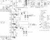
Have you noticed the pin numbers on the power amp PCB (Audio Unit AWK-008) schematic have a dot or two dots above them in their circles? The number itself is used multiple times, and pins differentiated by the dots above it.
I'm sorry, I'm not sure if I understand what I need to check on the schematic. Are you asking to check the number of dot in small circles like this ?
Screenshot 2021-01-01 at 16.47.04.png

Does adjusting VR4 (for left channel) change the bias voltage across R8?
Yes, the adjusting of VR4 change the bias voltage across R8.

I don't see any spec for the bias for the LX-440A or the SX-440. I have suggested 20mA (from AK observations) as a reasonable bias to start, which would be 10mVdc across one 0.5Ω emitter resistor.
I set the value for R8 and R9 to 10mV. The sound is good from the amp.
 
Maybe a little late (this time) but just in case:

PioneerLX-440ASchematic.jpg
 
Hi, I'm a little late to this forum discussion but I can throw in my 2 cents for what they are worth. With respect to calman46's comment on hum. I've just finished rebuilding a SX-440 and I observed hum in the output. In my case I it appeared that the top shielding of the audio board was insufficient. With the wood case cover on I could still hear hum and easily change the level by passing a ungrounded hand above the audio board. There is a shield over the equalizer stage and, in the cover, over the tuner board, but it doesn't fully extend to the audio board. So I fashioned an addition metal shield for the audio board which extends 3/4 of the way to the equalizer shield. Now I can only hear a bit of hum when I pass my hand over the slightly exposed portion of the audio board. In the preamp there isn't a lot of current and so I don't expect any appreciable heat build up.

Bias: In my case the bias, as found, was about 10mV. I've raised it to 20mV with minimal changes in the idle power used. After the rebuild with LED lighting in all lamps (replacing the burned out bulb in the dial pointer was a royal PIA) the SX-440 uses just 8 watts total in idle. This amplifier's stated 12wpc seems to be a little optimistic in my unit. I observe clipping at just under 10V_rms (at 400 and 1kHz) and so 10 or 11wpc (depends on frequency) seems more realistic. In the scheme of things that is really much a non-issue.

The last thing I was considering was addressing the slight pop when engaging the speakers. Originally I thought to splice in a small time delayed reed relay switch after the preamp output and amplifier input but that won't really help. For example, if I only turn on the speakers well after turning on the main power I still hear a small but noticeable pop. It only happens once but it it still a little bit of an annoyance. Does anyone have any simple suggestions. It isn't worth prototyping and building a complicated circuit.
 
I was thinking about try 3M 425 aluminum tape on the underside of the wood case over the audio board . I'm concern that adhesive might give out over time and the tape fall on the audio board. I couldn't find short enough staples locally. My Sx-440 has "nice" thump in the speakers on turn on. Even if I turn the speakers off on turn I still get a loud tick when the speakers are turn on. I'm using JBL 630's 4 ohm with 93 sensitivity . I'm not a tech but doesn't the thump come from C9 &C10 coupling caps? and would adding a circuit change the sound? The SX440 sounds very good as is.
 
I don't know about the 3M tape per se but soft aluminum roofers tapes usually has a pretty strong adhesive that I presume is intended to last as long as a typical roof. Short staple gun staples are easy enough to find on line. You might even do alright with a Swingline 747 staple. For the shield I used a small sheet of aluminum exterior flashing. The foil is easy to work and drill. It is also thin enough to be cut with a sturdy pair of scissors.

As for the thump on turn on, there is a very comprehensive AK discussion at https://www.audiokarma.org/forums/i...-and-an-hour-or-so-of-your-time.504673/page-2 which I found. This figure says it all https://www.audiokarma.org/forums/index.php?attachments/thyristor_switch_annotated-jpg.438754/ . Note that the snubber cap should be optional because Littelfuse thyristor datasheet claims they are not needed. I've just ordered the Q6030LT5TP to try it out.

It is my understanding that in general coupling caps are responsible for that thump when engaging the speakers. I am just wondering if the traic will change the SX-440's power on response. The Reed relay circuit contacts are very low resistance and, if between the preamp and the amp, they should not introduce any audible artifacts. But the thump when engaging the speakers won't be remedied. It might work if there was a way to have the speakers shorted to ground through some sort of low resistance bleed circuit which would turn off after a short time. Maybe one could use a normally open Reed relay and a series power resistor to keep the fuse from blowing. This is really beyond my ken.

Fyi: I used Arrow in this case because they were half the price of Mouser. Mouser does has cheaper shipping but I bundled it in which a number of other parts to make it worthwhile. I typically use Mouser because their website search engine is easier to use, the stock inventory is more consistent and they have a single shipping location in the US. Arrow, depending of the stock item, sometimes has prices that can be a factor of ten less than at Mouser. I've gotten 100V rated caps which were less than the the cost of the 10V version. It is a moving target because the pricing seems to change on daily basis.
 
Last edited:
. . . My Sx-440 has "nice" thump in the speakers on turn on. Even if I turn the speakers off on turn I still get a loud tick when the speakers are turn on. I'm using JBL 630's 4 ohm with 93 sensitivity . I'm not a tech but doesn't the thump come from C9 &C10 coupling caps? and would adding a circuit change the sound? The SX440 sounds very good as is.
Yes, it probably does come from those caps. The output caps will get some charge up on the output side as the power comes on, but that should drain away to ground through the headphones transformer and the feedback path through the 27kΩ resistor. Measure the dc voltage on the output fuse holder as you power on the unit (speaker switch off). You should see a short term voltage rise as the output caps charge to the power amps center voltage, then it should drop to 0vdc. How long does it take to get to 0vdc? Once it does get to 0v switch the speakers on and listen for your thump. If it does not drop to 0v you may have leaky caps. Have you replaced them recently?
 
Full recap and it sounds great. I hear those caps charge in the headphones ,if that is what I'm hearing ? Its only a few seconds .
 
Yeah, there is no getting around the bit of noise as the power comes up, unless you add a delay relay. You don't need a 'protection relay' as the cap-coupled output blocks DC. Its not a bug, it a feature :).
 
There is a shield over the equalizer stage and, in the cover, over the tuner board, but it doesn't fully extend to the audio board. So I fashioned an addition metal shield for the audio board which extends 3/4 of the way to the equalizer shield.
Hello Michael, I'm interested about your solution to decrease the hum. Can you add a picture of your additional metal shield ? Thanks
 
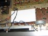
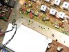
Hi, sorry for the delay but I am only now checking this thread now that I've had a chance to test the thyristor. Sadly it has little or no effect on the coupling cap turn on thump. However I noticed that when the headphones are plugged in the thump that occurs when first engaging the speakers by the on/off switch (following power up) was noticeably lessened(in partial answer to merlinsky). Turns out, at least in regards to any DC voltage, the headphones function as resistors that connect to ground. Each channel is in series with an ~100ohm resistor. With my headphones I measure a net resistance of about 133 ohms. So I patched in a pair of 100ohm resistors which are in parallel with the headphones and ground. It is a little more of a load on the amp (not much) but there is enough bleed so that there is now little or no thump when switching on the speakers even without the headphones. In addition to the metal shield I have a snapshot of the 100ohm bleed resistors.

IMG_3666.JPG IMG_3667.JPG IMG_3668.JPG
The metal shield could have been longer but it does improve things as is.

A timed DPDT relay inline with the coupling caps would likely work but I'm not going to go to that trouble.
I've never wired up a slow-start thyristor circuit but it doesn't look particularly difficult as seen in this link https://320volt.com/en/slow-startup-circuit-for-the-incandescent-bulb/
. At issue with the SX-440 is that the plug is not polarized. As for the basic circuit, just a 100 ohm resistor in front of the gate, it works regardless of the AC plug orientation. My knowledge base is a little thin and so I will need to wire up a prototype with LTspice to make sure I don't do anything too problematic.
 
Hi, sorry for the delay but I am only now checking this thread now that I've had a chance to test the thyristor. Sadly it has little or no effect on the coupling cap turn on thump.
The thyristor is not intended to cure a cap coupled amp's turn on noise. Its only job is to protect the (inadequate over time) power switch contacts.
A slow-start or soft-start circuit will not provide any benefit to the SX-440, It has a regular EI laminated transformer, not a toroid, and only a 1000µF main filter cap. It should not have a problematic high current input surge at power on. If it does eliminate the speaker noise it will only be because the power up is so slow you cannot hear it, so you will be waiting for the power supply to charge up. That delay may be more annoying that a little fuzz / rumble at power on. A unit that has a soft-start circuit closes its relay after just a few half cycle of the power line, a tenth of a second or less.
The un-polarized plug does not matter either, as neither side of the input power line is connected to the chassis.
 
The thyristor is not intended to cure a cap coupled amp's turn on noise. Its only job is to protect the (inadequate over time) power switch contacts.
Yep....this I now see after a bit of time on the proverbial "learning curve". I've found prototyping circuits useful in this respect but my LTspice only had a dummy symbol as a place holder for the "thyristor"...actually a triac. Finding the right directory to install the STMicro triac library files so that they could be opened proved surprisingly difficult. (Still it was far easier than finding posted and usable Ge transistor parameterizations) But no matter, once that was done I prototyped a number of posted soft-start circuits and the main effect I saw was a small time delay to turn on and, as you say, a delay of a few half cycles. There is much too learn.
It may be that a little fuzz is less annoying than the thump. It is particularly pronounced in headphones. For prototyping I decided it would be useful to put in the full power supply board circuit as well. I don't have the exact specs for the transformer coils and so those numbers were put in ad hoc. One thing I did notice was that the 11.5V and 24.5V DC rails actually take much longer to reach their operating voltages but maybe that was an artifact of my simulation. Thus a small delay is probably not a big deal all told.
As you mention, it may be worthwhile to add the triac switch to better protect the power switch contacts. I don't think it has been a big issue in the SX-440 but certainly other receivers have had real problems with this.
I note that my SX-440, based on the "standard" AK rebuild BOM list, now has a 2200uF main filter cap. Hopefully that won't overly stress the transformer. Obviously it will decrease the ripple proportionately. Even then I can still hear a small bit of hum through my headphones but not easily with speakers. Most people don't listen to them with their ear pressed up against the woofer.
There are a few simple modifications which I would like to try. Is it problematic to increase the gate resistor from 100 to 3.3K? According to the simulation the triac still switches on but the AC peaks are just a little less pronounced and the main filter cap charges up just a little more slowly with altered voltage steps. I'm not sure it is a major issue but I found I needed to include a small coupling cap to ground on the primary side of the transformer for the simulation to work.
 
Sometimes power supply rise delay and sequencing is deliberate, to reduce transient noise, and/or to prevent circuit lock up.
 
Any added delay in switching the triac makes it switch at a higher voltage and adds noise (and possibly distortion) on the AC line. The current through the power transformer, even during normal operation, is wildly non-linear though, so it might not matter. The gate has to have sufficient current to turn on the triac, look at the spec sheet for the minimum current needed. The AC peaks are when the power supply caps charge through the transformer and rectifier, I would think that a bad time to cause more non-linearity.
In the simulation every circuit has to have a (reference) connection to the common ground point. This is not necessary in real life.
 
Old thread, quick question on checking/adjusting bias on an SX-440.

Can someone please confirm the test points for me? The blue arrows were my first guess but I'd prefer not to guess. Thanks in advance for the assist.

IMG_0321.jpg Screen Shot 2022-02-20 at 1.07.48 PM.png
 
If you measure the voltage across both ends of one of those resistors, then perform a little math, you can deduce the current flow (E = I x R, I = E ÷ R). Measuring both resistors (currents) should result in the same indication for both, unless one of the components is leaking current to another part of the circuit.
 
Last edited:
Back
Top Bottom