• The move to the new server is done. There are some software and database maintenance updates in process. This has us passing the hat around to help out. We appreciate any donations. Seriously, even a dollar helps. The payment page may be found here - https://www.audiokarma.org/support.html

Pioneer SX-750 Popping/Crackling ReCap Question

K-Schick

New Member
Hey Everyone! I've been reading a lot on here and really appreciating the plethora of great info. This is my first thread.

I just took possession of my first vintage receiver, a Pioneer SX-750. I plan to use it for a headphone amplifier, as well as for speakers. Most likely a daily driver for my headphones at work. I would like to get this running nice and clean, and I may even try my hand at making and finishing a new wooden cabinet, or doing a wood veneer on it.

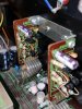
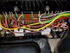
The receiver is surprisingly clean, but I can tell its been messed with and serviced prior. (There is a sticker in there from a service shop with a 1982 date on it). There are some pins with sloppily soldered on wires, a few pins with no wires (is this normal?), and the C17 & C18 Caps on the Power Supply AWR-099 were swapped out. Other than that, I cant find any other swapped out parts or replacements that are obvious to me. It sounds pretty good to my ear, and the tuner works great, but it has some intermittent popping and crackling going on. It comes and goes, sometimes sounding great for 20-30 mins before it shows up. Sometimes it happens immediately. Of course, when I try to take measurements with a DMM, the damn thing runs smooth as silk and wont pop or crackle.

The popping and crackling is always in the Right Channel, and is the same for all sources. It does not respond to Volume, or tone control changes. Since the popping/crackling is always in the Right channel, I believe the problem is not in the Power Supply section, and is most likely in the Power Amp section.

The Phono source has a constant lower level static and crackle, that is completely different from the intermittent pops and crackles on the other Source Inputs. I'm assuming the Phono Amp Section needs attention. TBH, that is not my top priority, as I'm not going to be primarily listening to LPs, but I would really like to try to tackle that (maybe later?) to get the receiver back to 100%, having zero issues, unless you all think I can easily fix it along with a full re-cap while Im in there.

I did a thorough deoxit treatment (per the super-informative thread by Arkay. Thanks a million for that, btw). I did every switch and knob twice, then I lubricated with faderlube. I also cleaned all the fuse connections (even thought there wasnt much to clean off). I cleaned the molex connector pins for the four Q1-Q4 transistors on the Power Amp as well.

I have also gone through the steps that MarkTheFixer listed in this thread:
http://audiokarma.org/forums/index.php?threads/pioneer-sx-750-right-channel-crack-popping.572125/
I exercised the VR2 trimpot in the Power Amp (that did not stop the popping), and later when I shorted the 26 & 27 pins, I did not hear any pops, but then again the damn thing quit popping after that, and I didnt hear another one for hours. (of course).

I have taken Voltage measurements on EVERY Pin on Power Amp AWH-046, Power Supply AWR-099, and the Power Supply Assy AWR-100. Nothing seemed more than 5-10% out of the recommended spec. If you guys thing its pertinent to list all of them Id be glad to, if that makes it easier to help me.

My DC Offset is L: 27mV, and R: 27 mV.

Voltage readings were all taken with the STV4H Diodes disconnected from the heat sinks, because I started to partially take this whole thing apart. (I hope this won't effect readings to a large degree). I can reconnect them to get more voltage readings if you guys think that's better/more accurate/safer for the receiver.

The popping and crackling did not change after any of this.

I'm gearing up to do a full recap of the Power Amp AWH-046, and the Power Supply AWR-099. I know that replacing some Transistors is a good idea too, but Im not sure of how many, or which ones are the most important for me to replace. Before I place a ReCap order, I just want to make sure that Im not missing anything else, or leaving anything out, like another board I should recap, a certain set of transistors, etc.

I've never recapped a receiver before, but hopefully Im on the right track, and some info from you guys will help set me off in the right direction!!

Any help, guidance, or suggestions are greatly appreciated! Thanks for your time!!
 
Register to hide this ad
Your particular unit has the alternate phono amp boards attached to the rear panel. One of my 750s has those, the other two have the SIP amplifiers.

Those boards (AWK-065) each have three 2SA725/726 transistors and a 2SC1313 transistor. Replace them all. They are on the Ten Most Wanted list for high failure devices. They typically exhibit the shot noise and static you are experiencing.

The 725/726s can be replaced with KSA992Fs and the 1313s can be replaced with KSC1815Ys. You might as well replace the 100µF cap on each board while it is exposed.
 
Awesome info!! Thanks!!

Ill definitely swap those out first, and Ill probably still look into doing a recap of those two boards I mentioned anyway. Should I look into any other boards to recap, or any other transistors while Im at it?

Thanks again! :)
 
Last edited:
Uhhh, Watthour, while there is a ksc1815, it isn't as low noise as the ksc1845

could the 1815 be a typo?

The complement to the ksc1815 is ksa1015, and had you mentioned that instead of the ksa992 I wouldn't have said anything.

The ksc1845 (120v) to ksc1815 (60v) is ok, the 750 is running them off of +22, -19 and that won't pop them...
 
Thanks for chiming in Mark. I appreciate the input.

So, just to be clear on what I need, I should be looking for a single KSC1845, and three KSA992F's to correctly compliment them?

Perhaps Watthour can clarify as well?


I was able to find a 512-KSC1845FTA, which was the only KSC1845 that I was able to find on Mouser.
Now, for the KSA992F's, the search function came up with four different model numbers:
512-KSA992FBU
512-KSA992FATA
512-KSA992FBTA

512-KSA992FTA

Are these all interchangeable for my application, or would you recommend one over the others?


Thanks to both of you for the detailed input. It is much appreciated!! :)
 
Yes, that may have been a fat-finger on my part. Look at the positions of the "1" and "4" keys and it should be apparent.

Each AWK-065 board has three 2SA725/726 devices and one 2SC1313 (or substitute) device. There are tow boards, once for each channel, so you would need a total of six KSA992Fs and two KSC1845Fs. Since the numbers you posted indicate you are shopping at Mouser, you may also want to consider a pair of 100µF capacitors to replace those on the boards.

The KSC1845F should work. The KSA992F is basically the same device in any of its variants. The F suffix is for the gain factor, and that is the critical variation. The BU is bulk-packaged, essentially loose pieces in a bag. The TA is tape strip packaged (ammo pack) for auto-insertion equipment, but they can easily be unmounted for hand insertion. I believe the A designation is for straight leads instead of pre-formed leads as are normally supplied in tape (ammo) packs. For replacement use it doesn't matter since the leads have to be bent to fit the mounting in either case. I don't recall what the B suffix identifies. However, whenever you notice a C suffix is generally means an alternate lead arrangement (center collector).

Whichever variation of the same gain factor is in stock and has the lowest price would be my choice.

As a matter of fact, it may be prudent to order a few extra of each transistor since there is another instance of the noise-prone devices in the SX-750 on the MIC amplifier which should also be replaced as a reliability issue. Ditto the 2SC1344 in that circuit which can be replaced with the KSC1845F. Since you already replaced C17 & C18 on the PS board you are in good shape there. A couple heat sink clips on the regulator transistors of the PS board might be helpful to keep things cool, but that's optional.
 
Excellent. Thank you for all that Watthour! :thumbsup:

To be clear, I personally did not replace those C17 & C18 Caps on the Power Supply board, someone else did prior to me owning the receiver. That was a bit confusing, sorry about that. It very well could have been done in 1982 when that shop had it, who knows. I figured I might as well replace those too, along with the others, as 1982 was still over 30 years ago.

Also, I forgot to mention this before, but I did have some popping while measuring my DC Offset, and it spiked up to around 80mV, then dipped down to around 15mV, before returning to around 27mV. Im not sure if that helps us at this point, but just thought I would share.

I just placed my order. Ive got a whole boatload of extra Transistors, I picked up a handful of those heatsinks you recommended, as well as Caps from Mark's Recap List from 11/24/2010 for boards: AWG-046, AWH-046, AWR-099, AWR-100, and, of course, the two AWK-065 boards. (A big thank you as well to Mark for all those organized part #s).

I will probably focus mainly on the two AWK-065 boards, the Power Supply board, and the Power Amp board for now. Ill see how I feel about doing the AWR-100 PS board, and the AWG-046 Tone Control board when Im done with those. I chose not to mess with AWE-073 board for now, and didnt order any Caps for it. (Hopefully I dont regret that). Im hoping there isnt anything major in there that is causing me problems. My tuner is working pretty great (needs to be recalibrated though, its slightly off). I will be using the Aux inputs daily, but the Aux Inputs work, so hopefully those caps are good. If you guys recommend changing out the few Caps that are in the Aux Input path, I may try to update my order, or order more Caps for that. Let me know what you guys think.

Ill update you guys on anything else that I find!

Thanks again!!

K-Schick
 
Yes, Mark does a fairly thorough job on his parts lists.

If the C17/18 replacements are 63V or better they may be just fine. The originals were only 50WV in a 48VDC circuit. That's just a little too close for long term reliability.
 
Yep, they were indeed the 63V variety! I think I actually read that on one of your older posts too. Good call, and thanks! ;)

I based my BOM off of that specific one from Mark that I mentioned, but for my BOM, I ended up combining information from a handful of different threads, two BOM lists, and of course all of the helpful info that you've been kind enough to share with me.

So, it sounds like you think I'm ok to leave those other boards/caps alone for now? I'm torn between (A) Trying to replace EVERY Cap in those BOM lists that I've found, and (B) Doing more of a 'Basic Re-Cap' to fix the problem that I'm having, and to take care of the main, most frequent problem areas.

I don't want to leave any obvious holes anywhere, but I figure I can start with the most important caps and transistors, and then see how it runs. Then go from there.

I'm really excited to crack into this and get moving on it. I feel like I've been reading and scouring the internet for what seems like forever, so it will be nice to bust out the soldering iron and get to work!

Thanks again for all your help and your quick responses Watthour! I'll keep you posted with updates!
 
My advice would be to do what is necessary to eliminate the crackle/noise and when you are satisfied it is resolved, recap the unit. That should minimize the potential for errors.
 
Well, I'll gladly take that advice then!

Also, I completely forgot to tell you this, but I took voltage readings on pins 4 and 7 on the phono boards and they seemed very close to spec. I don't know if that means that the transistors are ok, or of that only means they were 'behaving' during that time. Just thought I'd share.

I'll draft up a BOM for caps for the remainder of the unit.

Thanks :)
 
Hi again guys. Update:

Im hoping this weekend I have time to organize my 1st (partial) BOM that I received in, and get down to actually replacing some parts. In the meantime I am getting together a "Round 2" BOM to replace the remainder of the unit's Caps (AWM-094, and AWE-073).

Im using a combination of these two BOMs for 99% of my Re-Cap:

From 11-24-2010 (Im mostly following this, as it appears to be the latest list):
http://www.audiokarma.org/forums/index.php?threads/recap-question.334748/

From 10-05-2010 (Substituting any Out of Stock Items).
http://www.audiokarma.org/forums/in...ser-parts-list-for-recap.325599/#post-4043970

This has worked very well so far for my initial order, but now Im putting together a second BOM to ReCap the remainder of the unit. I have found that there is one Cap that is Out Of Stock on both lists, and I want to run my ideas for a replacement by you guys to make sure Im not choosing a blatantly incorrect item.

The Cap is for:
awe-073 c66 0.1 35v csza 0.1 50
Part Number from Mark's BOM is:
598-DSF050J
http://www.mouser.com/ProductDetail/Cornell-Dubilier/DSF050J104/?qs=8mJISjJf8gbkFHkfABgtPw==

Ive tried to find a few replacements that are Nichicon, Cornell Dublier, or Panasonic, Stacked Film Caps, since thats what Ive seen selected in these lists prior.

The CD Orange Drop is probably my first choice, though, only because Ive heard of them being used on guitar amplifiers, and people seem to really like them. They also mention in the datasheet that they can be used for: "power supplies and instrumentation to audio amplifiers and test equipment". If this is misguided hype, let me know, but they seem to fit the bill to my amateur eyes.

Here are the part numbers that I am considering:

647-QXK2E104KTPTZH

http://www.mouser.com/ProductDetail/Nichicon/QXK2E104KTPTZH/?qs=sGAEpiMZZMv1cc3ydrPrF5paIYTtxDrh3%2bgyFK6Blgk=

598-225P10491WD3
http://www.mouser.com/ProductDetail/Cornell-Dubilier-CDE/225P10491WD3/?qs=sGAEpiMZZMv1cc3ydrPrFx0L5xgIwAqUDnM80%2bBRyBg=

667-ECQ-E2104JB
http://www.mouser.com/ProductDetail/Panasonic/ECQ-E2104JB/?qs=sGAEpiMZZMv1cc3ydrPrF0%2bjlB8SXIRuNETHDW9yLSA=

647-QYX1H104JTP
http://www.mouser.com/ProductDetail/Nichicon/QYX1H104JTP/?qs=sGAEpiMZZMv1cc3ydrPrF4RExZn9GzDqVVmQwj0HKVA=


Thanks in advance for any guidance you folks can give me.
 
Last edited:
The Nichicon caps are too new to give a review on. The Orange Drop(225 series) is a bit large for the application. the ECQ is probably your best choice of the bunch right now.
 
Hello again everyone!!

Update and Question:

I am happy to report that I've finally made some progress on this Receiver! I have replaced the Transistors and the 100uF Caps on the Phono Input boards AWK-065 as directed, and that (so far) seems to have relieved the problems of the loud Popping and Crackling. I am SO happy about this!!
:D:beerchug:
Fingers crossed that it did indeed fix the problem. It was so intermittent, it is hard to tell that this point, but I have not heard it at all since working on it. Also, now the Phono Input sounds strong and clean with zero static.

I have also recapped the Power Amp Assembly board AWH-046.

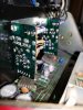
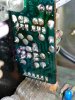
Everything has gone fairly smoothly, except for one issue, where I pulled a small section of the PCB trace off of one of the Phono Input boards. I found it when checking for continuity on all my new solder joints. I ended up getting lucky, and I was able to desolder the transistor leg, and I had JUST enough length on the transistor leg to bend it over and bridge the gap. I scraped off a small piece of the covered trace to reveal the copper, and then I soldered the end of the transistor leg to that. Its not the best looking thing in the world, but I have continuity now, so I was EXTREMELY relieved that I got it to work.

Question:
Now that I have done the Phono Boards, and the Power Amp Board, the unit sounds pretty good, but I noticed something when carefully listening. The Left Channel sounds different than the Right. The Right sounds full and articulate, but the Left sounds like it has a wet blanket draped over the speaker. The mids and highs are not as pronounced and articulate as they are in the right channel. They are there, but they just dont sound anywhere near as good, or as "sweet" as the Right channel. This is for all Inputs; Ive tried FM, Phono, and Aux, and Ive put the receiver in Mono mode while checking this. Its hard to hear when both speakers are going, but I noticed it right away when panning Left and Right during testing. I have tried swapping speakers.
Does anyone know what may cause this? I dont think its a Power Supply issue, as it is only in one channel. I was just curious if anyone else had experienced this issue.

Non-related question: Also, during testing I noticed that my signal from the Aux input bleeds very, very faintly into the Phono Input. For instance, if I have a signal going into the Aux Input, and then I switch to the Phono input, and I crank the volume on the receiver, I can faintly hear the signal being played into the Aux Input. Is this normal, or do I have an issue to address?


FYI: I have not re-capped the Power Supply Board, and I have not yet swapped the Transistors on the Mic Input as Watthour has suggested. the Mic Input Transistors are up next, then the Power Supply re-cap.


Please let me know what you guys think. As always, your help and knowledge is much appreciated!!

-K
 
Last edited:
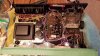
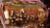
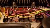
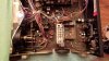
Pictures of the Phono Boards, and my repair. Not pretty, but it functions as it should. I cleaned the boards with Q-Tips after Soldering, so there are little fuzzies all over them.

20170102_023733.jpg 20170102_024116.jpg 20170102_023805.jpg
 
The Right sounds full and articulate, but the Left sounds like it has a wet blanket draped over the speaker.
When ever I read about these sort of statements I wonder if you were to use instruments to test, would you measure anything different between channels?
Is there anything different in the components that you used on both channels that could explain what you are experiencing? It is possible that you have a bad component, how to isolate it, is a problem.

Also, during testing I noticed that my signal from the Aux input bleeds very, very faintly into the Phono Input.
You are describing cross talk, it is there because of electrical and magnetic coupling in the switches and wiring to a lesser degree. It is measurable and audible as you attest too. The specs are not provided nor have I measured them, probably know one else has either than maybe the designer. Without this information you have no way of comparing your unit to another to determine if there is something out of spec on your unit. Thinking about what the actual cross talk number might be, probably in 50-70dB area I would think with these interlocking switches.
Is it a problem to be concerned about, I think not, just the facts and something you will have to live with.
It is possible if it is coupling between wires, then spreading them apart might help, but if it is in the switches you are out of luck. Even contaminants ( i.e. flux) on the pcb can cause cross talk or leakage between traces. These pcbs are simple designs, they have no ground planes that can help to eliminate certain coupling of signals.

CD orange drop caps are I believe polypropylene dielectric, which is usually a better grade of dielectric than polyester, but for audio, you are splitting hairs with selection of dielectrics. If you or anyone else can hear the differences in sound through a film cap, I salute you or laugh at you, I am not sure which.

Would have to say recapping the PS is probably one of the first thing that someone should do in a restore.

The Nichicon caps are too new to give a review on. The Orange Drop(225 series) is a bit large for the application. the ECQ is probably your best choice of the bunch right now.

Would you care to inform me and others how you would suggest to evaluate/review these caps in operation?
 
Last edited:
That set uses op-amp's in the tone circuit.
I would check all the voltages on the IC pins comparing between the good IC to the distorted channels IC. Be careful and insulate to the very tip of the meter probe so not to short to another pin.
Re-flow the entire tone circuit and revisit the controls with Deoxit.
Double check the components for correct position and indexing.
Think about swapping the tone output signals and eliminate the amps.
Not sure how a guy would do that.
Or:
After checking the above and it's still seems wonky, swap the IC's.
 
Last edited:
Back
Top Bottom