• The move to the new server is done. There are some software and database maintenance updates in process. This has us passing the hat around to help out. We appreciate any donations. Seriously, even a dollar helps. The payment page may be found here - https://www.audiokarma.org/support.html

Pioneer SX-950 receiver

Okay.I have removed all eight output transistors and tested them individually.They we’re all good.So are you thinking the predrivers,D-381 and B-536,as well as A-818 and C-1628?
Replace 818 and 1628 with KSA1381 and KSC3503. This always, always, always needs to happen. And the input pair.

This should have been done from day one. I have had countless 850/950's with issues from them.
 
Input pair being?? Would you also replace D381 and B-536,or are they fine?just thinking if I have the board apart….Thanks for the advice,appreciated!
 
Others can continue as you need single direction, but I find this real strange. Your left channel outputs from the amplifier board and to the protect board are showing -51V rather than 0 volts, or close to 0 volts. And the right channel outputs to the speaker and protection board are showing +42 volts rather than 0 volts or close to 0 volts.
Sort of saying that there is problems on both channels?
or could there be some miswiring from the restoration work? were any wires removed and connected on the amp board or on the power supply board.
I typically find and repair problems before replacing parts, that could cause issues. With problems on both sides such as yours, I would only start by measuring/testing transistors in question, and replace only if they read bad, (with an analog ohm meter or transistor tester. ) yes some transistors including the input pairs, and others can be candidates for replacement, but should be addressed after you have identified and fixed your problem. If the 818 or its pair are bad (open B to E, or shorted) by all means change, but be careful as the pinout for replacements will be different. Replacing lots of parts in a unit that already has multiple problems can add to the issues, making it so much harder to repair. But this is my opinion.
 
Last edited:
Not to my knowledge.I didn’t remove any wiring.The guy I bought it from said it powered on but no relay click and no sound output.Just trying to figure out what’s the problem with it.
 
with -51 v on 1 channel, and +42 on the other, will never allow for the protect circuit to allow relay click. And good thing because it would fry both speakers. As it didn't work, and unknown issues, I would double check everything. Making sure wiring is correct, making sure the outputs are in the proper locations (no swapping of npn and pnp's etc. I would lift out that amp board and look for areas of work, and checking any components to see if the were installed properly after replacement (transistors etc is B E C in the proper places). Is there any damaged foil traces?. Is there any connections that were accidently bridged to other connections. Are there any incorrect transistors installed? (PNP instead of NPN etc)
 
with -51 v on 1 channel, and +42 on the other, will never allow for the protect circuit to allow relay click. And good thing because it would fry both speakers. As it didn't work, and unknown issues, I would double check everything. Making sure wiring is correct, making sure the outputs are in the proper locations (no swapping of npn and pnp's etc. I would lift out that amp board and look for areas of work, and checking any components to see if the were installed properly after replacement (transistors etc is B E C in the proper places). Is there any damaged foil traces?. Is there any connections that were accidently bridged to other connections. Are there any incorrect transistors installed? (PNP instead of NPN etc)
 
If I Disconnect one wire on each side of the amp board, which is the right and left speaker outputs,The speaker relay clicks right on. When I touch either wire back on either power output board, The speaker relay immediately kicks out, protection. When I check C 1628,A-818 and even the predrivers,B-536 and D-381, some thing is over driving them, as I read 48 V 48 V and then 41 V,According to the schematic I should be reading 48 V 48 V, and 1.2 V
 
I swear all 8 output transistor tested good,but Maybe I’m missing something. The problem is the same thing on both channels
 
Verify that the output transistors are installed in the correct locations.

Once that is ascertained, there are some further checks to be performed on the drivers. This will require that the outputs are installed and NO speakers connected, powering the unit through a DBT, and voltage measurements in the main amp circuit.
 
Okay.So with the output transistors removed, I checked all the transistors across the output board from left to right:C-3503,-48,-48,-48.A-1381,47,47,47. D-381,46,46,46.B-536,46,41,46.C-3503,-48,-13,-48.A-1381,46,1.0,46.D-381,.47,40,1.0.B-536-.75,-40,-1.3.
 

Attachments

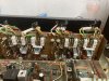
  • 6B622042-FC6E-4EEC-8B05-002E3238DC6D.jpeg
    6B622042-FC6E-4EEC-8B05-002E3238DC6D.jpeg
    142 KB · Views: 10
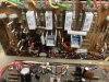
  • 1951B8F9-2E70-4BDA-BC8F-B89F21F55625.jpeg
    1951B8F9-2E70-4BDA-BC8F-B89F21F55625.jpeg
    151.5 KB · Views: 10
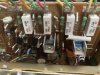
  • 95091BCE-2040-4842-8E6B-357CDD2BC430.jpeg
    95091BCE-2040-4842-8E6B-357CDD2BC430.jpeg
    122.1 KB · Views: 10
Check everything again.

Transistor orientation, solder bridges, and for any toasted resistors until the heat tubing.

Why didn’t you replace the trimmers?
Why is the 330uF cap huge?
Why aren’t the 1uF and 2.2uF both Nichicon KL?

The outputs were fine, you’d be blowing a fuse if they were in wrong.
 
Power supply:1-0V,2 and3,7.8V,4 and 5,20.0V,pin 6,and pin 7 48V,8 and 9,34V,pin 11,27V,pin 12,0V,pin 13,-13V,pin 14,-48.5V,pin-15,-17.5V.
 
Check everything again.

Transistor orientation, solder bridges, and for any toasted resistors until the heat tubing.

Why didn’t you replace the trimmers?
Why is the 330uF cap huge?
Why aren’t the 1uF and 2.2uF both Nichicon KL?

The outputs were fine, you’d be blowing a fuse if they were in wrong.
 
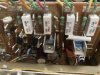
If the transistors in the positions for Q5, Q6, Q7, and Q8 are KSA1381E and KSC3503E, I believe the emitters and bases are swappped in the replacement installation. That would just about do it.
.
AWH-050Q5Orientation.jpg
 
Last edited:
I know the pin outs are different on the 1381‘s And the 3503’s compared to the 1628 and 818s.Sometimes it gets confusing on how the pins should go in on the board. I know Pioneer uses a lot of small arrows On their boards
 
Sometimes in the Pine-Ears the board artwork is incorrect or misleading. In the case of the AWH-050 board, they got it right. I marked Q8 for the way the transistor leads SHOULD be installed. If that is a KSC3503 (E or F) the lead orientation is E-C-B facing the front (labelled) face of the device. It's difficult to determine from the photo which side of the device is facing the camera.
 
Back
Top Bottom