Brivan
Well-Known Member
AC voltage to pin 7 of the PA3004 is 34mV. DC voltage to that same pin is 0v.i wanted to see the voltage AC AND DC for the AC detect pin when AC power is removed ...


AC voltage to pin 7 of the PA3004 is 34mV. DC voltage to that same pin is 0v.i wanted to see the voltage AC AND DC for the AC detect pin when AC power is removed ...
Gotcha. I've seen that posted before - I apparently was having a brain fart. No, no DBT connected. No speakers connected, no pre-out/in jumpers installed, wires to pins 4,5,6,7 & 8 of the protection board disconnected, no speakers selected, volume at 0.search for dbt on this site, not google, it is basically a 100-150W incandescent lamp in series with the ac line so that it acts as a fuse/limiter to limitthe line current in a shorted load condition.

am wondering how much AC is on the other pins ? with AC supply disconnected from the boardAC voltage to pin 7 of the PA3004 is 34mV. DC voltage to that same pin is 0v.
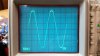
Interesting you're asking about that. I was just taking those measurements when I saw your question. With the AC connected, I get an expected AC signal on pin 7 of the PA3004, but I also get this waveform on pin 6 of the PA3004:am wondering how much AC is on the other pins ? with AC supply disconnected from the board
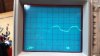
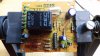
Yeah, that was kind of a surprise for me, too. My normal voltage reading with a PA3004 installed is -7.53vdc at pin 6. I'd love to have a complete schematic of the inner-workings of the PA3004. Right now, that's where my journey has ended. There is just nothing else I can find wrong. I have one more new PA3004 that will be delivered tomorrow. It's an extreme longshot, but maybe the noisy ground I had compromised the other PA3004s I had installed. Waaaay doubtful, but it's all I've got to go on, right now. Since I have a handy-dandy SIP socket installed, putting in a new one will take a few seconds.Nice PA3004 test jig.
I thought that pin 6 should be closer to -7.6VDC
That's a good point I hadn't really thought about. I assumed the PA3004 was causing a relay cycle based on the fact that I was still seeing the timing capacitor charge/discharge at pin 8 of the PA3004. I just disconnected the AC input from pin 1 of the protection board, then probed pin 3 of the PA3004 with my o-scope, and it's definitely showing a brief 12vdc output. So, the PA3004 isn't behaving correctly to a removed AC source.all i wondered is with it still cycling with AC disconnected it may have been getting the AC from elsewhere . it shouldn't be turning on the relay driver without it .
The timing capacitor does charge up, then it rapidly discharges at the same time pin 3 of the PA3004 gives a quick 12vdc pulse (the voltage is high, but I have Q2 removed. When Q2 is back in place the pulsed voltage is only 0.7vdc). The timing capacitor drops to about 1vdc, then rapidly discharges once it hits about 6vdc. I always have that timing capacitor cycle as long as the correct input voltages are provided to protection board pins 2, 9 & 10. And ground to pin 3. My apologies if I noted 0v at pin 8 of the PA3004 when I shouldn't have.I looked at post #115, the block diagram, Ct (pin 8) should be charging up to some dc voltage?, I do not think it should be zero V as in your case, there is a CC gen used to charge the ecap so it must be toast or the ecap is shorted or a really low C to cause it to cycle.

I had thought about that. The +65vdc and -50vdc power supplies might be a little tough to find - I don't think I have any that go that high, but I'll look. Maybe someone here can recommend a reasonably-priced one that would give me the ability to provide both voltages. I was also wondering if I could substitute in a protection board supply voltage from an external source without damaging the receiver.It appears that the PB is working correctly (except removing AC). Pin 3 goes to the + rail (~+12vdc) because Q2 is removed, so there is no current sink. If you put Q2 back in pin 3 will only increase to one forward biased base junction voltage (~+0.7vdc). But according the posts Q2 in or out makes no difference to whether the circuit cycles or not. Does anybody see a different effect?
Brivan, can you connect your spare Prot Board to power supplies, etc to simulate the SX-980 without actually connecting it to a Receiver? i.e. ground, +65vdc, +13vdc and -50vdc and see if it still cycles?
Okay, thanks. Caps have all been replaced, resoldered leads to all of the resistors 1 watt and above, resoldered leads to the four, large diodes. Powered on and still have charge/discharge of the timing cap and the brief 12vdc transition on pin 3 of the PA3004. Checked voltages to the protection board and the PA3004 - all basically the same as before.yes used for mech stability only
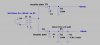
Thanks for the schematic! I checked my variac and it doesn't appear to have isolation between input and output. My newly-purchased SX-980 will arrive tomorrow, so I might wait to see if I can do some comparisons between it and my problem child. I thought I would have another PA3004 by now, but it's taking longer than expected.View attachment 1285537 You have a variac, you can whip together a low current supply with that and a few components. Be careful though, if your variac is not isolated from hot/neutral you may be at risk of electrical shock from this circuit.
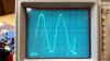
Well, we've had some results here, this morning. I've always noticed how clipped that 21vac looked on pin 1 of the protection board, as well as the .75vac on pin 7 of the PA3004. I checked the other AC lines coming from the transformer, and they're also less than perfect. Most show irregular peaks - not quite clipped, but not smooth, either. The clipping is most obvious on pins 12, 13 & 14 of the power supply board.It appears that the PB is working correctly (except removing AC). Pin 3 goes to the + rail (~+12vdc) because Q2 is removed, so there is no current sink. If you put Q2 back in pin 3 will only increase to one forward biased base junction voltage (~+0.7vdc). But according the posts Q2 in or out makes no difference to whether the circuit cycles or not. Does anybody see a different effect?
Brivan, can you connect your spare Prot Board to power supplies, etc to simulate the SX-980 without actually connecting it to a Receiver? i.e. ground, +65vdc, +13vdc and -50vdc and see if it still cycles?