

You are using an out of date browser. It may not display this or other websites correctly.
You should upgrade or use an alternative browser.
You should upgrade or use an alternative browser.
Pioneer Sx780 not working AC power problems.
- Thread starter Carlkits
- Start date
-
- Tags
- pioneer sx780

Carlkits
Member
To keep up with the diagnose.
After 8 pm the Vac readings drops a little
113 to 117 and was clicking, but like 3 clicks in one hour. I turn it off by 10 pm.
I turn it back at 5 Am was clicking intermittently, not able to use the receiver and the power was 113.
I tried again at 6.20 am and not one click, it's working and mine DMM is reading 118.
The R320 R319 solution definitely helped, but the problem still persists.
What should I try?
I notice that FM is also not working, only static.
Should I recap the power supply?
One oscilloscope would help?
After 8 pm the Vac readings drops a little
113 to 117 and was clicking, but like 3 clicks in one hour. I turn it off by 10 pm.
I turn it back at 5 Am was clicking intermittently, not able to use the receiver and the power was 113.
I tried again at 6.20 am and not one click, it's working and mine DMM is reading 118.
The R320 R319 solution definitely helped, but the problem still persists.
What should I try?
I notice that FM is also not working, only static.
Should I recap the power supply?
One oscilloscope would help?

Lowering that R319 1 meg resistance to increase the AC volts as seen at pin 7.
Pin 7 has an internal impedance of approximately 10,000 ohms for when doing voltage divider calculations
(R319 is R1 in the calculation, 10,000 ohms is R2 in the calculation)
Did we ever read the AC voltage at pin 20 of the GWK-118 board? The green transformer wire at the fuse board AWR-169 pins 5 or 6? Please do so.
Read the AC volts at pin 7 as well. All of these referenced to a bare metal chassis ground.
Perhaps we should change R319 to a multi-turn 1 meg pot. if one can be found.
then we could decrease resistance until it stops.
Your FM probably requires an antenna.
Pin 7 has an internal impedance of approximately 10,000 ohms for when doing voltage divider calculations
(R319 is R1 in the calculation, 10,000 ohms is R2 in the calculation)
Did we ever read the AC voltage at pin 20 of the GWK-118 board? The green transformer wire at the fuse board AWR-169 pins 5 or 6? Please do so.
Read the AC volts at pin 7 as well. All of these referenced to a bare metal chassis ground.
Perhaps we should change R319 to a multi-turn 1 meg pot. if one can be found.
then we could decrease resistance until it stops.
Your FM probably requires an antenna.
Carlkits
Member
Lowering that R319 1 meg resistance to increase the AC volts as seen at pin 7.
Pin 7 has an internal impedance of approximately 10,000 ohms for when doing voltage divider calculations
(R319 is R1 in the calculation, 10,000 ohms is R2 in the calculation)
Did we ever read the AC voltage at pin 20 of the GWK-118 board? The green transformer wire at the fuse board AWR-169 pins 5 or 6? Please do so.
Read the AC volts at pin 7 as well. All of these referenced to a bare metal chassis ground.
Perhaps we should change R319 to a multi-turn 1 meg pot. if one can be found.
then we could decrease resistance until it stops.
Your FM probably requires an antenna.
We never did make these readings.
I'm gonna make those readings, but one question from a noob user of a DMM.
How?
The receiver should be power on? The black pointer in the chassis and the red one on the pin?
And the FM, is not antenna, but first things first?
The receiver is clicking a little more than used, I did some readings whilst clicking and is around 117 vac.
it's probably not the lower voltage itself, but as much as the local power line's decreased ability to recover quickly from sags caused by increased loads.
Probably only a difference of a few cycles (tens of milliseconds, 17 per cycle) - but it's enough to trigger the PA3004 chip.
The older protect circuits, we could arbitrarily increase a small capacitor's value so that it rode out the sags, yet triggered reliably (but slightly slower) on power off.
On these we just have to modify it so that it will tolerate deeper and longer sags.
There are (expensive!!!) professional power line monitors that would report on and characterize power line disturbances.
-----------
to read ACvolts, set meter to AC volt range, touch black dmm lead to bare metal chassis ground, touch red lead to pin 20,
forget about reading pin 7 for now - the way things have occurred in this thread so far I'm not going to risk it.
Also the FM "static" but "is not antenna", also leaves little to do.
Probably only a difference of a few cycles (tens of milliseconds, 17 per cycle) - but it's enough to trigger the PA3004 chip.
The older protect circuits, we could arbitrarily increase a small capacitor's value so that it rode out the sags, yet triggered reliably (but slightly slower) on power off.
On these we just have to modify it so that it will tolerate deeper and longer sags.
There are (expensive!!!) professional power line monitors that would report on and characterize power line disturbances.
-----------
to read ACvolts, set meter to AC volt range, touch black dmm lead to bare metal chassis ground, touch red lead to pin 20,
forget about reading pin 7 for now - the way things have occurred in this thread so far I'm not going to risk it.
Also the FM "static" but "is not antenna", also leaves little to do.
john stumpf
Super Member
in the philippines i use an automatic transformer that is voltage regulated. they come here as new adjusted to 110vac output and 220vac output.they can be plugged into 110 or 220 by using the appropriate switch on the back. theres a trimmer inside that adjusts ac output that i set for 120 vac i use it on my computer but dont bother anymore on stereo's as ive found through experience i had no issues with NUMEROUS pioneers in this house including a sx 1080,880 and an 890 and many other pioneers too numerous to list with ZERO problems related to ac power. using any of my flukes and my ancient simpson 260,the power routinely dips to 110 t0 113 at night and never reaches 120 v ever. reading all you have tried it be interesting to know what was available at your shop and office. the airport radars and navaids might be of interest.i live in a bungalow 100meters from the former clark air base which is now a commercial airport but what floor are you on??? STILL i believe there is something wrong in your protection circuit that needs addressing. there WAS something about the sx880 protection circuit i read here some years back about a capacitor c418 47/16 being installed BACKWARDS. its interesting as that cap was installed with its positive to ground schematically either the schematic was wrong or the part was installed wrong as the silkscreen was wrong i dont remember. i DO remember that it was an 880 thread and NO ONE disputed this guys findings. a 780 is not an 880 i fully realize. but its possible the circuit is the same. the poster claimed it made the protection circuit too sensitive. im putting all this out there as there are several possibilities. ive never seen line frequency move around here much at but i did in hawaii on a small island. what makes those midrange pioneers hard to troubleshoot is that the protection and power supply (and everything else 'cept the tuner is on ONE board. i also think that 127 is too high but i also think that it should still work. i THINK the 780 has the overheating transistor problems like the 880 does it not? a faraday cage is a grounded screen envelop that shields the entire unit from rf radiation. easy to make with a couple of yards of aluminum screen wire grounded to a water tap.
Last edited:
Carlkits
Member
Hello guys
I was working abroad for the last month and did not worked in my receiver.
But I'm back and the problem persists.
I tried one senoidal transformer and nobreak but did not worked.
I even called the supply of power, and they adjust the power but the problems starts after 6 PM and stays until later.
Probably is something affect the quality of the power, but I guess the Sx780 is way sensitive, maybe something can be done.
I will ask again for your help.
My friends did I mark correct on the picture the pin20? I'm gonna make the readings
I was working abroad for the last month and did not worked in my receiver.
But I'm back and the problem persists.
I tried one senoidal transformer and nobreak but did not worked.
I even called the supply of power, and they adjust the power but the problems starts after 6 PM and stays until later.
Probably is something affect the quality of the power, but I guess the Sx780 is way sensitive, maybe something can be done.
I will ask again for your help.
My friends did I mark correct on the picture the pin20? I'm gonna make the readings
Attachments

Carlkits
Member
Helloin the philippines i use an automatic transformer that is voltage regulated. they come here as new adjusted to 110vac output and 220vac output.they can be plugged into 110 or 220 by using the appropriate switch on the back. theres a trimmer inside that adjusts ac output that i set for 120 vac i use it on my computer but dont bother anymore on stereo's as ive found through experience i had no issues with NUMEROUS pioneers in this house including a sx 1080,880 and an 890 and many other pioneers too numerous to list with ZERO problems related to ac power. using any of my flukes and my ancient simpson 260,the power routinely dips to 110 t0 113 at night and never reaches 120 v ever. reading all you have tried it be interesting to know what was available at your shop and office. the airport radars and navaids might be of interest.i live in a bungalow 100meters from the former clark air base which is now a commercial airport but what floor are you on??? STILL i believe there is something wrong in your protection circuit that needs addressing. there WAS something about the sx880 protection circuit i read here some years back about a capacitor c418 47/16 being installed BACKWARDS. its interesting as that cap was installed with its positive to ground schematically either the schematic was wrong or the part was installed wrong as the silkscreen was wrong i dont remember. i DO remember that it was an 880 thread and NO ONE disputed this guys findings. a 780 is not an 880 i fully realize. but its possible the circuit is the same. the poster claimed it made the protection circuit too sensitive. im putting all this out there as there are several possibilities. ive never seen line frequency move around here much at but i did in hawaii on a small island. what makes those midrange pioneers hard to troubleshoot is that the protection and power supply (and everything else 'cept the tuner is on ONE board. i also think that 127 is too high but i also think that it should still work. i THINK the 780 has the overheating transistor problems like the 880 does it not? a faraday cage is a grounded screen envelop that shields the entire unit from rf radiation. easy to make with a couple of yards of aluminum screen wire grounded to a water tap.
Yes, I guess the protect circuit is very sensitive.
I used 10 hours straight and was fine, but something triggers the relay.
You just make me want to REACH THROUGH the screen. The frustration is almost unbearable.
pin 20 is clearly marked below....
To COMPLETELY END this problem,
1. the 1 megohm r319 is disconnected
2. the 1 megohm R320 fixed resistor is removed
3. R320 is replaced by a 25 turn 1 megohm trimpot.
4. R320 trimpot adjusted until the problem stops.
start at 1 megohm and reduce the resistance until
the problem no longer occurs.. do not go lower than 100k ohms resistance.
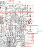
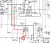
pin 20 is clearly marked below....
To COMPLETELY END this problem,
1. the 1 megohm r319 is disconnected
2. the 1 megohm R320 fixed resistor is removed
3. R320 is replaced by a 25 turn 1 megohm trimpot.
4. R320 trimpot adjusted until the problem stops.
start at 1 megohm and reduce the resistance until
the problem no longer occurs.. do not go lower than 100k ohms resistance.
Carlkits
Member
I'm sorry for my lack of knowledge.You just make me want to REACH THROUGH the screen. The frustration is almost unbearable.
pin 20 is clearly marked below....
To COMPLETELY END this problem,
1. the 1 megohm r319 is disconnected
2. the 1 megohm R320 fixed resistor is removed
3. R320 is replaced by a 25 turn 1 megohm trimpot.
4. R320 trimpot adjusted until the problem stops.
start at 1 megohm and reduce the resistance until
the problem no longer occurs.. do not go lower than 100k ohms resistance.
View attachment 2358464
View attachment 2358465
I see that I should have paid more attention.
I took the reading:
Pin 20 = 40 volts, it's a good number?
I bought the trimpod and I'm gonna take to the repair shop to make the adjustment.
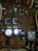
I took a photo.
Attachments

Brivan
Well-Known Member
I don't know why I didn't see this thread earlier, but I don't recall doing the modifications that MTF lists above. I went back through that massive thread and couldn't find anything:I have been researching this most of the afternoon.
Scoping the power would be my fondest wish, but I realize that is nearly impossible.
I have encountered this type of fault here in the forums at least twice, and they involved the PA3004 protection chip..
Did not necessarily understand WHY the fixes worked, but they WORKED.
One was with AK'er Brivan and his SX-980. He had a 21 VAC point being monitored by the protect.
The protect circuit had a series 1500 ohm resistor, and a grounded 10k resistor - making a voltage divider of 0.87 % . 21v x 87% is 18.2 VAC.
THAT point was connected to a 470,000 ohm resistor which was connected to pin 7 of the PA3004 chip.
What was done was the 1500 ohm resistor was bypassed/shorted and the 10,000 ohm resistor removed.
Thus feeding 21v AC to the 470,000 ohm series resistor and pin 7.
I propose disconnecting R320 (1 megohm : 1,000,000 ohms) from ground,
leaving R319 as a 1 megohm series resistor from pin 7 to approx 49 volts AC.
View attachment 2311002
My previous investigations suggested strongly that pin 7 of the PA3004 has an impedance of approximately 10,000 ohms, so the unit may NOT even turn on. (0.485v AC)
In that case take the opened end of R320 and connect it to pin 20, paralleling the 1 meg resistor with another 1 meg resistor. Thus turning the pair into a 500,000 ohm resistor.(0.978v AC)
https://audiokarma.org/forums/index.php?threads/pioneer-sx-980-protection-relay-kicking-out.834334/
From the OPs comments and others I've seen about their living accommodations, it adds more credence to the theory that the PA3004 IC is affected by the kind of harmonics that are injected into the electrical grid by frequency drives. Like the OP, I have more relay cycling problems at certain times of the day. This, no doubt, is due to equipment demands for changes in outside/inside building temperature. With an SX-780 I usually don't have relay cycling problems but the higher up in model number I go, the more certain it is that I'm going to have it. An SX-980 might give me problems, but a 1080 and above is guaranteed to have a cycling relay. About the only thing I can do is to make sure my offset and idle current are good, then use a jumper to force the relay to close, while I quickly go through some remaining tests. Once the receiver comes home, the cycling problem is gone.
The only cure that I've found (that I recall?) is by connecting through my DBT (shown in my signature pic), with all three 60-watt bulbs switched on. This is what allows me to work on a 780 or an 880 without problems, but a 1080 will still continue to cycle to relay. I'd like to try a suitable harmonic filter but I haven't found one that isn't insanely priced.
It might be worth the OP inquiring to his apartment manager if frequency drives are being used. My guess is they are.
Carlkits
Member
Thanks @Brivan , I'm tired of that clicking.
I used on my beach house and worked 4 days straight without a single click.
So I was able to purchase one sx980 and I'm gonna sell the Sx780.
My friend is testing the Sx780 and is perfect.
And the Sx980 I'm my house, same outlet, same transformer is working great.
Maybe was bad luck on me.
I used on my beach house and worked 4 days straight without a single click.
So I was able to purchase one sx980 and I'm gonna sell the Sx780.
My friend is testing the Sx780 and is perfect.
And the Sx980 I'm my house, same outlet, same transformer is working great.
Maybe was bad luck on me.
Carlkits
Member
Good night
And now the sx980 is clicking.
The Sx780 on my friends house, is working beautifully, and my new to me sx980, do not work between 6 and 22 PM.
But now testing a different receiver, it's clear that the receivers are working fine.
I ll try solve the problem of bad wiring, and if I resolve the issue I ll post the results in here.
I wanna thank all you guys for the help.
I learn a lot.
I hope this thread one day help others.
And now the sx980 is clicking.
The Sx780 on my friends house, is working beautifully, and my new to me sx980, do not work between 6 and 22 PM.
But now testing a different receiver, it's clear that the receivers are working fine.
I ll try solve the problem of bad wiring, and if I resolve the issue I ll post the results in here.
I wanna thank all you guys for the help.
I learn a lot.
I hope this thread one day help others.
They all have the same circuit. Replacing the 1 meg resistor in the voltage divider with a 1 meg trimpot, and STARTING at 1 meg adjusting downwards until the false triggering stops.
Remember that the pin 7 input looks like a 10,000 ohm input resistance to ground.
This type of interference can be generated by ANY type of high frequency switching power supply, as it's demands are tightly coupled to the power line frequency and phase.
I have dealt with this type of interference before, and it was responsible for my acquisition of spectrum analyzer capability long ago.
It essentially shut down my Analog TV reception during different time periods during the day - which corresponded to the local elementary school's largest attendance computer science classes. Once school let out, everything started working again. Only the digital TV transition saved me. This was BOTH over the power line and over the air.
Since then, they no longer use CRT monitors - which were the offenders.
Remember that the pin 7 input looks like a 10,000 ohm input resistance to ground.
This type of interference can be generated by ANY type of high frequency switching power supply, as it's demands are tightly coupled to the power line frequency and phase.
I have dealt with this type of interference before, and it was responsible for my acquisition of spectrum analyzer capability long ago.
It essentially shut down my Analog TV reception during different time periods during the day - which corresponded to the local elementary school's largest attendance computer science classes. Once school let out, everything started working again. Only the digital TV transition saved me. This was BOTH over the power line and over the air.
Since then, they no longer use CRT monitors - which were the offenders.
Carlkits
Member
They all have the same circuit. Replacing the 1 meg resistor in the voltage divider with a 1 meg trimpot, and STARTING at 1 meg adjusting downwards until the false triggering stops.
Remember that the pin 7 input looks like a 10,000 ohm input resistance to ground.
This type of interference can be generated by ANY type of high frequency switching power supply, as it's demands are tightly coupled to the power line frequency and phase.
I have dealt with this type of interference before, and it was responsible for my acquisition of spectrum analyzer capability long ago.
It essentially shut down my Analog TV reception during different time periods during the day - which corresponded to the local elementary school's largest attendance computer science classes. Once school let out, everything started working again. Only the digital TV transition saved me. This was BOTH over the power line and over the air.
Since then, they no longer use CRT monitors - which were the offenders.
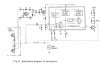
Which one I disconnect, and replace with the trimpod?
Attachments


Bill Ferris
Lunatic Member
Might I suggest a minimum of 6 amp rated Trip-Lite brand automatic 120 volt mains voltage regulator (AVR) between your 220v to 120v stepdown transformer and the receiver.
Not only will it maintain ~120v to the receiver, but also has very effective power line surge/spike protection & RFI/EMI noise filtering as well.
I`m not comfortable with the VA/wattage rating (I think 750 VA) of the OP`s 220 to 120 volt step down transformer for that sized receiver !
And would personally prefer a minimum 1000 VA rating myself, to better handle turned up receiver peak current demands which would cause higher voltage drops within the stepdown transformer causing sound quality performance restrictions due to mains starvation, as I call the effect, barring any other internal problems in the receiver..
Just some thoughts from past low mains voltage equipment problems experience, after reading this thread.
Good luck with sorting out the low voltage mains power problems.
Not only will it maintain ~120v to the receiver, but also has very effective power line surge/spike protection & RFI/EMI noise filtering as well.
I`m not comfortable with the VA/wattage rating (I think 750 VA) of the OP`s 220 to 120 volt step down transformer for that sized receiver !
And would personally prefer a minimum 1000 VA rating myself, to better handle turned up receiver peak current demands which would cause higher voltage drops within the stepdown transformer causing sound quality performance restrictions due to mains starvation, as I call the effect, barring any other internal problems in the receiver..
Just some thoughts from past low mains voltage equipment problems experience, after reading this thread.
Good luck with sorting out the low voltage mains power problems.
R8, 470kWhich one I disconnect, and replace with the trimpod?
Carlkits
Member
Might I suggest a minimum of 6 amp rated Trip-Lite brand automatic 120 volt mains voltage regulator (AVR) between your 220v to 120v stepdown transformer and the receiver.
Not only will it maintain ~120v to the receiver, but also has very effective power line surge/spike protection & RFI/EMI noise filtering as well.
I`m not comfortable with the VA/wattage rating (I think 750 VA) of the OP`s 220 to 120 volt step down transformer for that sized receiver !
And would personally prefer a minimum 1000 VA rating myself, to better handle turned up receiver peak current demands which would cause higher voltage drops within the stepdown transformer causing sound quality performance restrictions due to mains starvation, as I call the effect, barring any other internal problems in the receiver..
Just some thoughts from past low mains voltage equipment problems experience, after reading this thread.
Good luck with sorting out the low voltage mains power problems.
Thanks Bill
Nowadays I use one one 1kva pure sine wave senoidal transformer, which I think can handle the sx980.
Here in Brazil, on AVR costs like 500 dollars, but I bought something custom made for help purified the power in my home, gonna upload one photo.
And I followed the instructions of the greats technicians from AK and the receiver is on the repair shop to add the trimpot.
Probably one week for now I ll be back with results.
Attachments
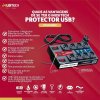

Since my command of Portuguese is not very good, I had to translate the specifications of the device you linked:
https://audiokarma.org/forums/index.php?attachments/img-20211015-wa0008-jpg.2368485/
USB 2 x 1300mA
Protection: Neutral Line / Line-Line / Ground-Line / Neutral-Ground
Rated operating voltage: 127 / 220 Vca @50 / 60 Hz (with identifier)
Maximum load current - IL: 10A
Maximum Power - WMAX: 2200 W
Maximum continuous operating voltage - UC: 275 Vca / 350 Vcc
Maximum discharge current - IMAX: 17kA @8 / 20 μs (Line-Line or Line-Neutral)
Total discharge current - ITOTAL: 62kA
Typical response time: 19 µs
Operating temperature: - 40 °C...70 °C
Input connection: Cable with plug 2 P + T (ABNT NBR 14136) 10A
Length of the input cable: 1.6 m
Output connection: 8 Outlets, 2 P + T (ABNT NBR 14136) 10A
Packaging: Flameproof plastic box
Display LED with voltmeter
DPS Class: II
Protection technology: Metal oxide varistor (MOV), GAS Discharge Tube (spark gap)
Color: Black
It appears that the device will discharge large transients, but not be of much use for moderate overvoltage or undervoltage conditions.
As is the case for most similar surge protection devices, the MOVs are there to handle the heavy work if any real transients come through, while the gas discharge tube handles the moderate (most frequent) lower voltage transients. I did a study of these a few decandes ago and determined that for most of these units the MOV was almost useless, and any really useful clamping was done by a neon lamp connected as a power indicator. It's alsmost as effective as a dedicated gas discharge tube, if not quite as robust.
https://audiokarma.org/forums/index.php?attachments/img-20211015-wa0008-jpg.2368485/
USB 2 x 1300mA
Protection: Neutral Line / Line-Line / Ground-Line / Neutral-Ground
Rated operating voltage: 127 / 220 Vca @50 / 60 Hz (with identifier)
Maximum load current - IL: 10A
Maximum Power - WMAX: 2200 W
Maximum continuous operating voltage - UC: 275 Vca / 350 Vcc
Maximum discharge current - IMAX: 17kA @8 / 20 μs (Line-Line or Line-Neutral)
Total discharge current - ITOTAL: 62kA
Typical response time: 19 µs
Operating temperature: - 40 °C...70 °C
Input connection: Cable with plug 2 P + T (ABNT NBR 14136) 10A
Length of the input cable: 1.6 m
Output connection: 8 Outlets, 2 P + T (ABNT NBR 14136) 10A
Packaging: Flameproof plastic box
Display LED with voltmeter
DPS Class: II
Protection technology: Metal oxide varistor (MOV), GAS Discharge Tube (spark gap)
Color: Black
It appears that the device will discharge large transients, but not be of much use for moderate overvoltage or undervoltage conditions.
As is the case for most similar surge protection devices, the MOVs are there to handle the heavy work if any real transients come through, while the gas discharge tube handles the moderate (most frequent) lower voltage transients. I did a study of these a few decandes ago and determined that for most of these units the MOV was almost useless, and any really useful clamping was done by a neon lamp connected as a power indicator. It's alsmost as effective as a dedicated gas discharge tube, if not quite as robust.
Carlkits
Member
Since my command of Portuguese is not very good, I had to translate the specifications of the device you linked:
https://audiokarma.org/forums/index.php?attachments/img-20211015-wa0008-jpg.2368485/
USB 2 x 1300mA
Protection: Neutral Line / Line-Line / Ground-Line / Neutral-Ground
Rated operating voltage: 127 / 220 Vca @50 / 60 Hz (with identifier)
Maximum load current - IL: 10A
Maximum Power - WMAX: 2200 W
Maximum continuous operating voltage - UC: 275 Vca / 350 Vcc
Maximum discharge current - IMAX: 17kA @8 / 20 μs (Line-Line or Line-Neutral)
Total discharge current - ITOTAL: 62kA
Typical response time: 19 µs
Operating temperature: - 40 °C...70 °C
Input connection: Cable with plug 2 P + T (ABNT NBR 14136) 10A
Length of the input cable: 1.6 m
Output connection: 8 Outlets, 2 P + T (ABNT NBR 14136) 10A
Packaging: Flameproof plastic box
Display LED with voltmeter
DPS Class: II
Protection technology: Metal oxide varistor (MOV), GAS Discharge Tube (spark gap)
Color: Black
It appears that the device will discharge large transients, but not be of much use for moderate overvoltage or undervoltage conditions.
As is the case for most similar surge protection devices, the MOVs are there to handle the heavy work if any real transients come through, while the gas discharge tube handles the moderate (most frequent) lower voltage transients. I did a study of these a few decandes ago and determined that for most of these units the MOV was almost useless, and any really useful clamping was done by a neon lamp connected as a power indicator. It's alsmost as effective as a dedicated gas discharge tube, if not quite as robust.
Funny thing is even with low voltage, the sx980 works great, if I unplugged and let run on batteries, the vac drops to 80, but the click stop immediately.
I hope the issue is solved with the trimpod and the filter.