Larry: If you have access to a set of early Sams, try volume 46 folder 11. This has the supressor that Scott used. Both the Fisher and the scott supressors were lincesed by H.H.Scott so the Scott diagram will be close enough so you can get ideas of what Avery had in mind. Good luck BTW my supressor has the same probelm as yours.. I have not made any attempt to troubleshoot it. All I did was to replace all the caps. have not had time to check resistors. Too many German radios in the house to attend to.


You are using an out of date browser. It may not display this or other websites correctly.
You should upgrade or use an alternative browser.
You should upgrade or use an alternative browser.
Possible Model 24 Rehab
- Thread starter larryderouin
- Start date

What i found is Volume 46 Folder 21 has 2 suppressors. 149381 and 149382 Now to figure out which one.
Nice BLUE GLOW fro mthe 6L6WGB's.

Getting some funny readings from the Mica caps in the suppressor. There are 5, with 2 values, and I can't make complete sense of the "DOTS"
The two big ones, following the arrows LEFT TO RIGHT ACROSS THE TOP then down and across right to left (at least thats how numerous mica cap charts show).
I'll write them out as shown on the cap.
RED, BLACK, BLACK,
GREEN, SILVER, BROWN. I surmise these are probably 2000pf? 10% tolerance?
One test out @ 1853pf the other 2337pf
The small ones are
BROWN,BLACK BLACK
RED,SILVER, BROWN And these are 1000pf??
All within 30pf of 1000.
The Large ones are SOLAR branded and the small ones are Cornell Dublier.
Getting some funny readings from the Mica caps in the suppressor. There are 5, with 2 values, and I can't make complete sense of the "DOTS"
The two big ones, following the arrows LEFT TO RIGHT ACROSS THE TOP then down and across right to left (at least thats how numerous mica cap charts show).
I'll write them out as shown on the cap.
RED, BLACK, BLACK,
GREEN, SILVER, BROWN. I surmise these are probably 2000pf? 10% tolerance?
One test out @ 1853pf the other 2337pf
The small ones are
BROWN,BLACK BLACK
RED,SILVER, BROWN And these are 1000pf??
All within 30pf of 1000.
The Large ones are SOLAR branded and the small ones are Cornell Dublier.
Attachments

I'm about to toss the Expander and compressor. The compressor has what looks like a DUAL TRIMMER between the 3rd and 4th tubes. Ceremic housing with what looks like rf trimmers on it. The housing is cracked in at least 2 places. I still get sound from it in one position but the other 3 positions are so noisy (rice krispies) you can't hear the LP.
On the expander, I figured out that Either it was miswired at the factory, or the input labels were installed incorrectly. The suppressor input is marked Crystal only and the other is not marked (decal wore off). I traced from the inputs and the inputs are corect but the decals are wrong. I made 2 different label that are correct and powered up. About a minute later I hear what sounds like sizzling and boiling noises from the expander transformer. Touched it. Hotter than the hubs of hell. Unplugged, opened it up and a small amount of wax had dripped out. Gotta recheck every resistor and cap now. The tubes are fine.
Disconnected the secondaries, and plugged in and took voltages. 7.8vdc, 6.9vac, and 280vac per side to CT. OK. So I went back over what I had done recently and found the 39K resistor hadn't been soldered in the tower. (you have to unsolder everything to the 6sk7 just to get to the tower backside. Broke out the labels and the camera. Removed the tower after disconnecting all but the heater lead. Redid the 39K resistor (R16), replaced R14(120ohm) & R17(100Kohm). Ohmed out the socket before reinstalling and verified labels already on it. Reinstalled with heatshrink on all leads. Now I have almost no sound from the expander with the suppressor in line. With the suppressor out of line I get about 2-3 db down from straight from the preamp to the phono input on the tuner. I've rotated 3 different known GOOD 6SK7GT's thru it. No 6SL7 so subbed a 6sn7. No difference. Same with the 6H6 and the 5Y3. I'm gonna pull that tower off tomorrown and completely disassemble it, and rebuild the whole socket for the 6sk7.
I'm wondering if it might be a viable option to do away with the Volume expander and Noise compressor and just run the 24 as a bare bones unit with a modern RIAA preamp. Am I thinking the only thing I'd really have to worry about is balancing the heater load from the 12at7, 3 6sk7's and a 6sq7. or just the 12AT7? or just disconnect the B+ to the suppressor unit and leave the heaters connected. Then run the phono off the outboard preamp which I proved out by disconnecting the input and output from the old preamp, and connecting them to the outboard RIAA preamp, then straight to the Tuner phono input.
On the expander, I figured out that Either it was miswired at the factory, or the input labels were installed incorrectly. The suppressor input is marked Crystal only and the other is not marked (decal wore off). I traced from the inputs and the inputs are corect but the decals are wrong. I made 2 different label that are correct and powered up. About a minute later I hear what sounds like sizzling and boiling noises from the expander transformer. Touched it. Hotter than the hubs of hell. Unplugged, opened it up and a small amount of wax had dripped out. Gotta recheck every resistor and cap now. The tubes are fine.
Disconnected the secondaries, and plugged in and took voltages. 7.8vdc, 6.9vac, and 280vac per side to CT. OK. So I went back over what I had done recently and found the 39K resistor hadn't been soldered in the tower. (you have to unsolder everything to the 6sk7 just to get to the tower backside. Broke out the labels and the camera. Removed the tower after disconnecting all but the heater lead. Redid the 39K resistor (R16), replaced R14(120ohm) & R17(100Kohm). Ohmed out the socket before reinstalling and verified labels already on it. Reinstalled with heatshrink on all leads. Now I have almost no sound from the expander with the suppressor in line. With the suppressor out of line I get about 2-3 db down from straight from the preamp to the phono input on the tuner. I've rotated 3 different known GOOD 6SK7GT's thru it. No 6SL7 so subbed a 6sn7. No difference. Same with the 6H6 and the 5Y3. I'm gonna pull that tower off tomorrown and completely disassemble it, and rebuild the whole socket for the 6sk7.
I'm wondering if it might be a viable option to do away with the Volume expander and Noise compressor and just run the 24 as a bare bones unit with a modern RIAA preamp. Am I thinking the only thing I'd really have to worry about is balancing the heater load from the 12at7, 3 6sk7's and a 6sq7. or just the 12AT7? or just disconnect the B+ to the suppressor unit and leave the heaters connected. Then run the phono off the outboard preamp which I proved out by disconnecting the input and output from the old preamp, and connecting them to the outboard RIAA preamp, then straight to the Tuner phono input.

I mean nothing against Avery's efforts to produce the highest quality sound at the time, but to the audio aficionado today, the whole Compressor/Expander excursion can really be put in the same category as the SpaceXpander adventure was that Fisher also had.
Granted, the dynamic range of the old 78 records was quite limited, and in theory, a compressor/expander could help to reduce noise and enhance the dynamic range of that medium. In reality however, it all too typically comes off like so many FM stations that try to modulate their carrier 100%, 100% of the time, with the rather unnatural pumping and pulsing such circuits can create.
There is the thought of restoring those units for restoration's sake, to make the unit be what it was -- always important from a $$ standpoint as to its worth. On the other hand, a candid conversation with the owner as to what they want versus what sources they will be using may just arrive at the complete elimination of the Compressor and Expander units from the signal chain. The phono preamp -- DC heater and all -- could then be operated directly from the main tuner chassis, meaning that the old add on equipment would no longer be connected into the circuit at all.
Now here I go again, so slap me if I'm out of line here, but the external phono preamp could even be modified to represent the typical modern Fisher 12AX7 RIAA preamp circuit, to really bring the phono section of the 24 into the new millennium.
I'm not abdicating any particular direction to take. There's the authentic approach and (frankly) the practical approach, and likely other options in between. I'm just glad its you wrestling with this problem rather than me!!!
Dave
Granted, the dynamic range of the old 78 records was quite limited, and in theory, a compressor/expander could help to reduce noise and enhance the dynamic range of that medium. In reality however, it all too typically comes off like so many FM stations that try to modulate their carrier 100%, 100% of the time, with the rather unnatural pumping and pulsing such circuits can create.
There is the thought of restoring those units for restoration's sake, to make the unit be what it was -- always important from a $$ standpoint as to its worth. On the other hand, a candid conversation with the owner as to what they want versus what sources they will be using may just arrive at the complete elimination of the Compressor and Expander units from the signal chain. The phono preamp -- DC heater and all -- could then be operated directly from the main tuner chassis, meaning that the old add on equipment would no longer be connected into the circuit at all.
Now here I go again, so slap me if I'm out of line here, but the external phono preamp could even be modified to represent the typical modern Fisher 12AX7 RIAA preamp circuit, to really bring the phono section of the 24 into the new millennium.
I'm not abdicating any particular direction to take. There's the authentic approach and (frankly) the practical approach, and likely other options in between. I'm just glad its you wrestling with this problem rather than me!!!
Dave
As I have the schematic for the expander, I'll concentrate on it for another day. I'm also gonna talk to the owner about options.
1.) keeping the original preamp (only) in the signal path and running it direct. The problem there is 33's sound flat and tinny. There are no dynamics. (for 78's)
2.) keeping the original preamp powered up for the heater, and bypassing it (signal path, the putting a outboard RIAA preamp in the signal path. (for 33's and 78's). Granted the RIAA will color the 78's but it won't sound like a 1960's Toshiba pocket am radio.
3.) sending the noise suppressor and expander out to an old tube tech that knows about these (which just might be fairly impossible to find). Or conversely just installing them "dead" and keeping them just for aesthetics sake.
Modding the original preamp to RIAA spec sounds interesting. There ain't a lot of room inside the preamp box itself. I suppose it could be done tho. This may be an option. Mainly a few resistors and caps right? I think I have a couple of PEC's from an 800-C that I pulled and replaced with a board with discrete 1% components. Matter of fact i have a discrete board already populated that matches a PEC, part for part. Now to figure out how to connect it all up. I have a 65 Ambassador Tuner/preamp/amp I use for parts and it has the 50817-12(2 lead) PEC's in it. Maybe take one of them out and connect it up. The 800-C pec is a 50817-3 (3 lead) which I have a discrete board for.
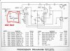
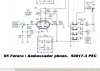
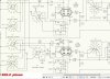
Pictures of the two circuits and the 24's preamp. Note that the preamp i have DOES NOT have R1-R2, C1, S-1. Other than that it's pretty much the same.
24 preamp

65 Futura / Ambassador preamp circuit. 50817-3 PEC

800-C Phono Circuit 50817-12 PEC

1.) keeping the original preamp (only) in the signal path and running it direct. The problem there is 33's sound flat and tinny. There are no dynamics. (for 78's)
2.) keeping the original preamp powered up for the heater, and bypassing it (signal path, the putting a outboard RIAA preamp in the signal path. (for 33's and 78's). Granted the RIAA will color the 78's but it won't sound like a 1960's Toshiba pocket am radio.
3.) sending the noise suppressor and expander out to an old tube tech that knows about these (which just might be fairly impossible to find). Or conversely just installing them "dead" and keeping them just for aesthetics sake.
Modding the original preamp to RIAA spec sounds interesting. There ain't a lot of room inside the preamp box itself. I suppose it could be done tho. This may be an option. Mainly a few resistors and caps right? I think I have a couple of PEC's from an 800-C that I pulled and replaced with a board with discrete 1% components. Matter of fact i have a discrete board already populated that matches a PEC, part for part. Now to figure out how to connect it all up. I have a 65 Ambassador Tuner/preamp/amp I use for parts and it has the 50817-12(2 lead) PEC's in it. Maybe take one of them out and connect it up. The 800-C pec is a 50817-3 (3 lead) which I have a discrete board for.
Pictures of the two circuits and the 24's preamp. Note that the preamp i have DOES NOT have R1-R2, C1, S-1. Other than that it's pretty much the same.
24 preamp
65 Futura / Ambassador preamp circuit. 50817-3 PEC
800-C Phono Circuit 50817-12 PEC
Attachments
Circuit wise, it shouldn't be that hard to convert the preamp. Physically, well that may be a different story. It just depends on whether you want to "contaminate" the unit with a SS add on or not.
If you do want to do away with the phono preamp, then simply replace the 150 ohm 10 watt resistor in the amplifier chassis with a 50 ohm 5 watt resistor, and you're done. Use the Compressor, Expander, and Preamp for memorabilia!
Dave
If you do want to do away with the phono preamp, then simply replace the 150 ohm 10 watt resistor in the amplifier chassis with a 50 ohm 5 watt resistor, and you're done. Use the Compressor, Expander, and Preamp for memorabilia!
Dave
That may be a way to go. I've got a 50ohm 10W ceramic here. Or is the 5w more appropriate?
If we do go with the outboard and disconnect all the original stuff, I need to do something to tone the volume on the phono down, say put an attenuator or pot in the unit somewhere between the outboard preamp and the tuner, the cartridge puts out 10mv, then the outboard puts out I don't know how much , but the sound gets distorted (I believe it's probably clipping) about 1/2 to 2/3 of the way to max Volume. Supposedly the PHONO and TV Inputs are Line Level, but I'm of the opinion the line level was much less then compared to now.
I'm waiting to hear on what she wants to do. I'm thinking about 250K pot internally.
Or maybe just a 3 to 5 db attenuator between the preamp and the tuner phono input.
I don't mind "contaminating" it with the board. But ultimately it's up to the owner what gets done.
If we do go with the outboard and disconnect all the original stuff, I need to do something to tone the volume on the phono down, say put an attenuator or pot in the unit somewhere between the outboard preamp and the tuner, the cartridge puts out 10mv, then the outboard puts out I don't know how much , but the sound gets distorted (I believe it's probably clipping) about 1/2 to 2/3 of the way to max Volume. Supposedly the PHONO and TV Inputs are Line Level, but I'm of the opinion the line level was much less then compared to now.
I'm waiting to hear on what she wants to do. I'm thinking about 250K pot internally.
Or maybe just a 3 to 5 db attenuator between the preamp and the tuner phono input.
I don't mind "contaminating" it with the board. But ultimately it's up to the owner what gets done.

A thought here, if your phono pre has only the 1 meg from grid to ground on the input circuit the loading is going to be very screwy. The switch rig puts a 10k in parallel to the 1 meg, so your cartridge would see just a CH under 10k for resistive loading. A more modern cart would want about 47k there. It would probably be very tinny if you have 1 meg resistance vs the 47k it expects. With about 10k, it'll probably be very dull and weak sounding with a more modern cart. The old VR2 was a fairly hot generator and it worked into something like 10-15k.
I paralleled a 10K on the 1meg, and it did open up some. Not a whole lot but some. I DID notice something. The preamp inside my R-3 chassis on the '51 coronet is very similar. And that one sounds full bodied with a 1meg grid to ground on pin 7.
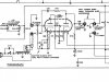
R-3 Phono circuit. Compare this to the Model 24 preamp a couple of posts up.

R-3 Phono circuit values;
R68 1moHm 1/2w
R69 680 ohm 1/2w
R70 1500ohm 1/2w
R71 100k 1/2w
R72 120k 1/2w
R73 2.2mohm 1/2w
R74 1k 1/2w
R75 68k 1/2w
C66 Mica 0.003mfd
C67 Film .002uf 600V
C69 Film .1uf 600V
I'm also using a GE VR on this one. Doesn't look like there is any EQ in this one either.
R-3 Phono circuit. Compare this to the Model 24 preamp a couple of posts up.
R-3 Phono circuit values;
R68 1moHm 1/2w
R69 680 ohm 1/2w
R70 1500ohm 1/2w
R71 100k 1/2w
R72 120k 1/2w
R73 2.2mohm 1/2w
R74 1k 1/2w
R75 68k 1/2w
C66 Mica 0.003mfd
C67 Film .002uf 600V
C69 Film .1uf 600V
I'm also using a GE VR on this one. Doesn't look like there is any EQ in this one either.
Attachments
Larry -- Those are virtual carbon copies of each other, so something somewhere must be amiss if the same preamp in your R3 gives the impression of a full response, while the one in the 24 seems very restricted. Were you otherwise comparing with the same speaker system and TT/cartridge?
The EQ is primarily provided by way of NFB path established by the 120K resistor and .003 cap connected in series from the plate of the right section back to the cathode of the left section. The small interstage coupling cap also gets in on the action as well.
Dave
The EQ is primarily provided by way of NFB path established by the 120K resistor and .003 cap connected in series from the plate of the right section back to the cathode of the left section. The small interstage coupling cap also gets in on the action as well.
Dave
phono preamp
When I got my 24 B the phono preamp was missing so i installed a solid state preamp on the underside of the changer mounting board. Tried going through supressor and expander and compared this to direct connection to tuner chassis. direct to tuner won out. slight improvment. Cartridge used is gold G.E. VR2. regards Norman
When I got my 24 B the phono preamp was missing so i installed a solid state preamp on the underside of the changer mounting board. Tried going through supressor and expander and compared this to direct connection to tuner chassis. direct to tuner won out. slight improvment. Cartridge used is gold G.E. VR2. regards Norman
Yep. Same speaker and TT/Cart. I've got the 24 sitting on the coronet and extended the speaker connection to the 24 and also the Cartridge Interconnect up to the 24's preamp.
WELL The IDIOT's Rule the PREAMP. Someone had been in it after the factory and before me, and replaced R14(22K) with a 68K. And then buried it BEHIND C-4, between it and the T-strip. There were lots of gloppy solder joints in the thing. No wonder I couldn't see it with just my glasses. So I broke out the Magnifier with the Flourescent lamp, changed C3 and got to C4. There's this 68K resistor sitting back there. I went and verified it on the schematic (NO 68K!) So I traced it out 6 ways to Sunday and came up with R14. Pulled my last 22K 1/2W out and replaced it, C3, C4, and R8 which was also buried behind C4.
HOO YAH! At 1st it was kind of of weak still, so I broke out some 12at7's and started rolling (turning off and waiting 5 minutes between each). Funny thing is the 6201 that was in there was one of my strongest reading 12at7 types. Maybe it doesn't like 6201's. It's now at the same level @ 2/3 on the volume as it was before at max volume on the pot. It's just a bit flat, as is the R-3 but volume is good now. Bass and treble resonse is fair on phono. I suspect that's due to a lack of a RIAA circuit. But it sounds a lot better now. I compared the R-3 against it and the R-3 is a little louder, but not by much. So NOW THE PREAMP is WORKING as it's Supposed to.
Thank God, Avery FISHER, Dave Gillespie, Gadget, and VAGUY1 for the help, ideas, nudges, and swift kicks. Appreciate it guys. We'll see what the owner wants to do as far as the Expander and compressor.
Larry
WELL The IDIOT's Rule the PREAMP. Someone had been in it after the factory and before me, and replaced R14(22K) with a 68K. And then buried it BEHIND C-4, between it and the T-strip. There were lots of gloppy solder joints in the thing. No wonder I couldn't see it with just my glasses. So I broke out the Magnifier with the Flourescent lamp, changed C3 and got to C4. There's this 68K resistor sitting back there. I went and verified it on the schematic (NO 68K!) So I traced it out 6 ways to Sunday and came up with R14. Pulled my last 22K 1/2W out and replaced it, C3, C4, and R8 which was also buried behind C4.
HOO YAH! At 1st it was kind of of weak still, so I broke out some 12at7's and started rolling (turning off and waiting 5 minutes between each). Funny thing is the 6201 that was in there was one of my strongest reading 12at7 types. Maybe it doesn't like 6201's. It's now at the same level @ 2/3 on the volume as it was before at max volume on the pot. It's just a bit flat, as is the R-3 but volume is good now. Bass and treble resonse is fair on phono. I suspect that's due to a lack of a RIAA circuit. But it sounds a lot better now. I compared the R-3 against it and the R-3 is a little louder, but not by much. So NOW THE PREAMP is WORKING as it's Supposed to.
Thank God, Avery FISHER, Dave Gillespie, Gadget, and VAGUY1 for the help, ideas, nudges, and swift kicks. Appreciate it guys. We'll see what the owner wants to do as far as the Expander and compressor.
Larry
Don't forget to include yourself it there Larry. I can't think of anyone I know that would want to take on such a challenge in the first place!!
Dave
Dave
Yeah I do take on some crazy stuff. I think I might have gotten in over my head with the Expander/suppressor tho. Anyway I heard back from the owner. Basically it was do whatever makes it sound best. So I'm gonna take my outboard preamp (inexpensive Bozak Madisson which I don't use) with me and A/B the preamps for her and Husband. If she goes with the RIAA, I'll change R28 and note the location on a picture of the amp for her with the 150ohm resistor. Gotta get a 3db attenuator for between the RIAA preamp input and Cartridge. The preamp is rated for 6mv input and the cart 10mv output. Need to tone it down a little so the amp doesn't get overloaded and distorts/clips.
Thanks Dave
Larry
Thanks Dave
Larry
got a -3db RCA line level attenuator. The hookup is GE VR Mono Cart (running 8.5mv) --> -3db attenuator ---> phono preamp (6mv input max)---> phono input on Model 24. No expander or suppressor. YES!!!!!! Sounds like a rig with a built in RIAA preamp. This is the best sounding of the options. Even on 78's. As the preamp has stereo in and output's I'm using one side, with a shorting plug on the un-used side's input. 2 screws to mount the preamp and it's in. But I'll hook up the original preamp direct to the 24, bypassing the compressor and expander for comparison. I have a 50ohm 10W resistor to replace the 150ohm to balance out the circuit after removing the original preamp, and just leaving it hanging for posterity. All packed up and ready for it's trip home. 7am start time should put me there around 10-1015. Then hook it up, figure out an antenna for it, and ske-daddle home. If I remember my camera, I'll take pictures of it completed. I ran it 5days straight (120hours), with no problems. No hum that I can hear. FM and AM are pretty good. SW is limited probably due to lack of antenna for it.
We'll see what happens tuesday.
We'll see what happens tuesday.
The VR does have a lot of drive. I like mine, shame they just aren't compatible with stereo records. It is a fine 78 generator though. I may have to try it with a -3 db attenuator though. Currently its fed into a broadcast phono pre that Naptown Rob gave me. I expect those are designed to handle a fairly hot cartridge, though I don't actually know the specs on it. Seems to sound OK though.
No doubt the owner will be absolutely blown away with the job you did Larry! It's always so neat when you can take a Fisher, maintain all those wonderful qualities that make a Fisher what it is to begin with, but make it better, which you did. It's really great that such a rare and important piece of Fisher history was rejuvenated by someone who cared so much and took the time to really do it right.
Congrats on a job well done!
Dave
Congrats on a job well done!
Dave