• The move to the new server is done. There are some software and database maintenance updates in process. This has us passing the hat around to help out. We appreciate any donations. Seriously, even a dollar helps. The payment page may be found here - https://www.audiokarma.org/support.html

Possible Model 24 Rehab

Ok. So what your saying is I need to look inside the amp, and verify from the CT, to pin 9 and also verify that R27 is ok.

I verified the integrity of the cables from the preamp all the way back to the tuner, and then out the 12 pin main cable to the connector. Everything checks out there. So the problem is in the amp.

I'll take a look and see.

Thanks Dave.
 
Dave; YOU SIR, are a WIZARD!

Pulled R27 out of circuit, and it's FLAT OUT OPEN! I checked the other 10W resistors in the amp (1-250 ohm and 2-15Kohm) and all are within 3% of nominal.

Replaced a bunch of 47K and 1K, more than 10% out of spec.

Just made the order for all of the 10W resistors. Might as well give her an amp that'll last for her grandkids.

Once I get those, I'll get a 6.3V transformer, and we can do the P.I. Adjustment on the thread. Help some other guys while we're at it.

Larry
 
Good job finding the open resistor -- however, there's still a bit of a mystery, as if the resistor was completely open, then:

1. NOTHING could have worked on the unit at all unless the phono preamp was plugged in so as to have a path for current to flow through between the center tap of the HV winding, and ground. Remember, the only way the CT of the HV winding connects to ground is through the heater of the 12AT7 phono preamp tube, and R27. With an open R27, and no phono preamp tube connected, then no path exists between the HV CT, and ground, so the unit will not work at all.

2. On the other hand, with the preamp connected, and R27 open, it means that ALL current flow for all circuits of the unit is flowing through the heater of the 12AT7 phono preamp tube, which could possibly burn it out, without the presence of R27 to act as a shunt so as to limit current flow through the tube. If R27 was in fact burned out, then check the continuity of the full heater in your 12AT7.

A couple of other points to consider: If you were expecting an AC voltage on the heater, and therefore had your meter was set to read AC volts, then your meter would in fact read very little if anything since it is a DC voltage powering the heater. Make sure to set your meter to DC volts when chasing this rascal down.

Finally, rough calculations indicate that for the full 12AT7 heater to have about 11 vdc across it (a figure Fisher is rather fond of for powering their 12.6 volt phono preamp tubes) when a 150 ohm resistor is connected in parallel with it, then there needs to be about 200 ma of current flow through the heater/resistor combo.

Again, rough calculations indicate that the output stage alone is drawing about 92 ma, while both the AM and FM tuners could easily draw another 90 ma, since they both appear to operate all the time -- even when TV or Phono inputs are selected. Then, throw in some audio/muting/ and indicator tubes, and you could see 200 ma soon enough.

Just some added thoughts to help you get this one all sorted out!

Dave
 
Funny thing . It's been running WITHOUT the preamp, and the 150ohm. The tube is fine. I have one tester that checks 12A_7's at 6 v and one that tests @ 12 V. All of the tubes I've put in it are fine. What's weird is, the way it's connected on the amp is between the CT of the trans and the pin 9 lead, not as shown on the schematic. If you put R27 on the left side of the Pin 9 lead, that's how it is on the amp. Probably makes no difference.

That lead from Pin 9 may also branch off for the noise suppressor as it's also part of that power cord. But the suppressor has only been hooked up for short times, and is currently disconnected, and the rig runs fine without it.
 
Last edited:
Since the schematic then is obviously not a match to the build, is there any chance you could provide some good detail shots under the amp/power supply, of the circuits in question?

Dave
 
From post #42.

attachment.php


Let me know if you want me to quarter the amp.

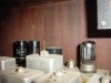
150ohm is the BLUE resistor. tubes in pairs top to bottom are
5Y3's
6l6WGB
7A4's x2(The left one is the P.I. Right is the AF Driver)
7a7 (Muting Relay driver off by itself on the right lower above the 12 pin block ).

The green wire from the 150 ohm to the 12 pin block (lower right) is to pin9.

The resistor is connected to Pin 1 on the rectifier as a tie point, with the pin 9 wire and the CT wire back to the transformer.
 
Last edited:
Thanks, Larry. OK, there is only ONE possible explanation that covers all the symptoms you are describing, which is:

1. The 12AT7 phono preamp tube heater does not light, and

2. The unit operates in spite of the fact that the blue 150 ohm 10 watt resistor was completely open.

The only way both of those things can happen at once, is that pin 1 on the rectifier tube (the tie point you mentioned) has somehow become grounded. That would let it play in spite of an open 150 ohm resistor, and also kill the phono preamp tube heater at the same time.

The short could be anywhere in the amplifier chassis, the umbilical cord between it and tuner chassis, within the tuner chassis, the umbilical between the tuner and the expander, the umbilical to the phono preamp, or the phono preamp chassis itself.

This should be easy to find however. With the unit off, connect your ohmmeter between the rectifier tube pin 1 tie point and ground. This will certainly show a short or nearly so if the above symptoms listed are accurate.

Now, disconnect the phono preamp chassis, then the expander, then the tuner, until none of them are connected together. At some point, the short should vanish, telling you where to look. If the short remains with everything disconnected, then the short is in the amplifier chassis. Going in reverse, whatever you first connect up that displays the short is where the problem is. Basically, if the blue 150 ohm resistor is open, and the 12AT7 phono preamp tube is removed from its socket, but everything is all connected together, then the pin 1 rectifier tube tie point should read as a completely open circuit to ground.

Let us know!

Dave
 
I've got it all apart so the obvious thing was to test pin 1.

5Y3 tube in.....OPEN
5Y3 tube out...OPEN

Took pin 1 apart. Pin 9 and green wire OPEN to chassis.
CT is OPEN to chassis

Connected Pin 1 all back together, then tried the TUNER chassis. Pin 9 on plug to chassis.....4.50ohms!

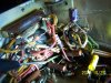
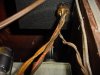
I found the culprit. There was a 100uf/ 50V Solar "Mini cap" sitting on the terminal strip, that had the positive on the ground terminal, and the NEGATIVE on the terminal for PIN 9 (outer one with 2 greens and a multi colored beige). Look in the lower left hand corner.

BEFORE
attachment.php


AFTER The terminal strip Extreme RIGHT Terminal is our friendly pin 9 to pin 2 junction. There are two green wires and the multi-colored Beige wire(pin 9 lead.) The Greens, one goes to pin 2 at the 6 pin plug which is below the large ohmite(R72) on the back wall(pin 2 is at 6:00 in the picture), the other green dead ends (literally!) on a terminal strip out of the pictures to the left. (Probably used in the 24A for filament power or whatever.
attachment.php

attachment.php

So I replaced it with a 100uf/50V lytic (Same for Same as usual). Looks like it shorted as soon as power applied. No capacitance and a dead short, because the 150ohm resistor burned up and this was the only point to ground, so it went chernobyl, shorted, and Voila! No 12V to heater and the unit still works (except the preamp).

I'm just wondering if that cap is really necessary, and if not, then I'll pull it and not worry about it. I take the cap out of circuit and the ground to pin 9 ceases to exist.

EDIT: I just realized that's C124. Am I correct in presuming that since I was getting
(NEGATIVE) - 0.925 volts before that this is a NEGATIVE 12V (-12VDC) so the polarity is normally reversed on C124.

 

Attachments

  • 100_4664.jpg
    100_4664.jpg
    124.3 KB · Views: 27
  • 100_4669.jpg
    100_4669.jpg
    112.6 KB · Views: 5
Last edited:
Correct Larry -- The positive lead of C124 should be grounded.

No doubt you likely tried the unit for the first time without the phono preamp connected. With R27 open and no heater in circuit, that let the voltage rise across that cap to a very high level, no doubt causing an internal (near) short, allowing the unit to run, but the heater would not run of course when the phono preamp was plugged in.

Replace the resistor and the cap, and there ya go. The cap is in fact necessary, as it prevents an audio signal from developing across R27, that would otherwise develop due to the use of a class AB output stage. It also provides a degree of filtering for the DC heater power to the phono preamp tube as will.

You're getting it on the run now!!

Dave
 
Preamp

Larry: On the 24 you are fixing is there a junction box mounted on the cabinet " roof" with a transformer in it? mine has one and a 4 prong socket. the supressor has a 4 wire cable that plugs into it. on the rear of the tuner chassis is a socket right next to the multi wire cable going from the tuner to the amplifier.a 2 wire cable plugs into this socket and goes to the "box on the roof" I think that b+ goes up this wire into the "box on the roof" and then to the 4 wire cable to the supressor.Confused? Hope not. With all this I have no idea how the preamp was wired in, unless the supressor had the preamp built in.. For a model that not that many were made, there were a lot of different versions of the same radio. Norman
 
Norman. According t the owner I have everything except the cabinet, the speaker, and the two headshells with GE VR (single stylus) cartridges.

This one is probably a later version. The "box on the roof" is supposed to be the phono preamp that the suppressor feed with the 2 wire cable in an earlier model.

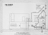
I think this will answer your questions. I believe it's for either the 24 or 24A.
attachment.php


In this version, The filament supply gets it's power from the main unit thru the 4 wire cable, then out to the Suppressor via the 2 wire cable. This was for either the 24(external preamp) or 24A (internal phono preamp) that wasn't originally ordered with the Noise suppressor.

Mine is setup in that the preamp takes the place of the Filament supply,
Which has only the 4 wire cable to preamp, and a 4 wire cable to the suppressor. The input's and output's come from the turntable and out to the suppressor (or the expander if you wanted to delete the suppressor, or direct to the phono input on the tuner). It works any way, as long as there is a working preamp.
 

Attachments

  • Fisher DNS Chassis And Wiring Layout.jpg
    Fisher DNS Chassis And Wiring Layout.jpg
    102.9 KB · Views: 59
"Box on the roof"

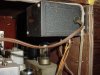
Larry: on my 24B the BOR(box on the roof) is mounted on the top rather than the side. unlike your picture my set has a 3 way socket mounted on the roof. it gets power from the amplifier 110 v. socket, and feeds the BOR, the expander the rest is like your "24
 
Last edited:
Norman; I did some more digging and In the manual there is a statement that the suppressor could be bought separately for those units that were not built with it at the factory. Which I surmise would come with a separate filament power supply as it would have been a slightly different unit. The one I have here was factory ordered, and doesn't have the Filament POWER SUPPLY nor does it have the 2 wire cable entering the bottom of the suppressor as the power is supplied from the main unit.

I believe your's was originally ordered without the suppressor, and was added later. Can you look at the speaker and pull the EIA code off it. it should be 220xxx with 3 numbers replacing the x's. That'll give us an approx 3-4 month window of build date.

Can you take some pictures of the area in question on yours?
Larry
 
24 diffrences

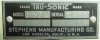
Larry: could not find eia# on Stephens speaker. my tweeter is intermittant.am curious if it is the voice coil or a cap in the crossover. am sending a few photos including a close up of the nameplate of the speaker. also my supressor has an extra tube (7H7) than yours.?????? also no 110 volt socket on tuner.
 

Attachments

  • DSC00001.jpg
    DSC00001.jpg
    47.3 KB · Views: 16
  • DSC00002.jpg
    DSC00002.jpg
    84.7 KB · Views: 16
  • DSC00003.jpg
    DSC00003.jpg
    80 KB · Views: 14
  • DSC00005.jpg
    DSC00005.jpg
    54.9 KB · Views: 17
  • DSC00006.jpg
    DSC00006.jpg
    77.3 KB · Views: 15
  • DSC00004.jpg
    DSC00004.jpg
    74.7 KB · Views: 17
change the cap 1st on the tweeter. If it's the V.C. you are gonna have problems finding a replacement or someone to change it out. There should be a ink stamp on the rim of the cone basket.
What's the serial # on the 24B? This one here is 1612.
Your DNS is different than the one i have here. Unfortunately, we don't know which one is the earlier version. The owner did verify that it was ordered with the DNS, DVE, preamp, and Jensen H-510 and bought from FISHER directly and shipped to the store in town, and her father had it delivered. It's as it was in spring 1949.


My mistake. I meant the Amp for the 110V. The BLACK BOX is the Filament supply for the DNS. The extention cord outlet on the top of the cabinet( Pic 2) would be indicative of a dealer or field installation. It probably plugs in to the 110VAC outlet on the amp. Other than slight differences in the way the cables are laid out your's looks as the drawing shows. With the cables the way they are I just wonder how much of that black box is transformer supply and whether the Turntable preamp is inside?
 
serial #

Larry; The serial # on the 24 B is 1526. Had the box on roof opened to change out dry rotted power cord. no preamp inside only transformer. Maybe the extra tube in the scratch supressor is the preamp???will look into the cap in the crossover tomorrow. Good luck on your project. Norman
 
So yours got made about a week or so before mine if they were making at least 100 per week. Which makes it a 1949 model.
 
The 7f7 is a Hi-Mu Twin Triode (probably equivalent to 12ax7?) so yeah it may very well be the preamp tube.
 
The 7H7 is a loctal Semi-remote cutoff pentode, equivalent to the more commonly known 6SG7 in the (typically metal) octal base family. As a pentode then, it is unlikely that this tube is the phono preamplifier tube -- which where ever it is located -- likely has its heater run off of DC current as well. Therefore, look for a dual triode tube that has a 12 volt 150 ma heater configuration.

Dave
 
Back
Top Bottom