• The move to the new server is done. There are some software and database maintenance updates in process. This has us passing the hat around to help out. We appreciate any donations. Seriously, even a dollar helps. The payment page may be found here - https://www.audiokarma.org/support.html

Possible Model 24 Rehab

Thanks Sam. It was a challenge, but I felt I could handle as much as I could up to the limit of my experience and knowledge. I told the owner that if it had alignment problems I would not be able to do much with it if anything. But I'd give it a shot.

And I didn't have the right schematics for 1/2 of the stuff.


Considering it's been sitting in her living room for the last 20 years or so, and the last she remembered was the radio quit, but the phono worked, it's not that bad. Mainly dirty, lot's of pipe cleaners and Deoxit, some tubes, and a complete recap. Lot's of wax buildup on the bottoms of the chassis's.

It's opening up a bit now. It does sound good right now. Once all the problems are solved, I'll run it 24/7 for a week with no problems before i turn it over to the owner.

Larry
 
Very nice Larry! Lot of work that I know you're happy you're getting a return on now.

Does the tuner have an AM antenna with it? Not just a long wire, but the classic air loop antenna? Invariably, those are part of the RF stage tuning circuit; if it's missing -- depending on how it is connected into the circuit -- it will either kill the whole AM band, or at least the upper portion. Sometimes, manufacturers mounted such antennas on the inside wall of the cabinet, in which case, you (obviously) wouldn't have it then. Just a thought!

Great job!!

Dave
 
Thanks Dave; It's been a fun challenge. The scariest part for me is powering them up for the 1st time. I'm always afraid I connected something wrong.

It probably has an air loop in the cabinet. IT's got the usual screws on the back panel for antenna's (FM and AM). I can hook up the one I have in the R-3's Cabinet.

Listening to WWCR on Shortwave 9350kc (9.35mc) (Note for you young'un's; kc and mc was changed to kHz and mHz in the mid 60's about the time the Conelrad marking were taken off radios) out of Nashville. Edgar Bergen and Charlie McCarthy show for about an hour. I was getting goodebumps, as I used to listen to them when I was wearing short pants.

I get this funny feeling the owner will end up standing in a large puddle of tears as she hears her dad's pride and joy playing again. Just glad she decided to get it running again for whatever reason.

Now I've got to get cracking on that phono preamp and figure out why I have no heater voltage to the 12AT7.
 
Last edited:
AM dropping at the top of the band almost sounds like a weak oscillator, but if it runs on shortwave that may not be the case. May just be alignment related. If the antenna trimmer is too far off kilter it will tend to knock out one end or the other of the band.


I've been looked at funny a lot of times for using "cycles" instead of hertz. I read a lot of old books when I was young and learning about radio stuff. That was the term used in the books from the 40s and 50s that I was reading, so its what stuck.
 
I've been looked at funny a lot of times for using "cycles" instead of hertz. I read a lot of old books when I was young and learning about radio stuff. That was the term used in the books from the 40s and 50s that I was reading, so its what stuck.

I spend more time on the sub helping with the 50's and 60's era radio, sonar and Radar gear, and it's all in cycles. Plus what i grew up with.


Tomato, tomatoe, potato, potatoe.....It all comes out the other end brown and smells like an outhouse.
 
Larry, how goes the photo preamp diagnostics? I've been trying to follow along on the schematic but the power connections in the tuner chassis are difficult to understand. Does what your seeing agree with what's on the schematics?

I can't remember if I sent you the operating instructions so I'll post them in case the antenna section sheds any light on the AM situation.

AnniversaryModelOperatingInstructions-1.jpg
 
Pretty much, although you have to decipher which connection goes to which model 24. This one has the 6 pin connector that is at the bottom of the amp schematic in the center. But the other end at the preamp is a 4 pin (same as J3 in the right corner). The 6 pin also feeds the Noise suppressor.

I haven't done anything yet today, and more Honey do's. Maybe tonight.

Thanks for the operating instructions. I'll print those out too for the owner.

Larry
 
loop antenna

Hi all I have a 24B I don't think it had a loop antenna. no sign of one in the schematic. none in the speaker box. I guess Fishers idea was if you can afford 1250 plus for this radio you could afford to have a tech come to your house and install either an attic antenna or an outdoor one. BTW my phono preamp I got on ebay last year does not have the same plug layout as to power. I feel that fisher came out with several varations of this preamp. also to whomever opened up the preamp in the pictures, what is the secret to getting inside it? also to whom was looking for a schematic of the scratch supressor. if you have a sams index look up H.H.Scott dynamic scratch supressor. should be somewhere below issue 100. E.H. Scott used one as an accessory for their 800B console. it was mounted on the "roof" of the changer compartment with a long shaft for the 5 position rotary switch.. hope this helps Norman
 
Does it have a ferrite bar antenna on top of the tuner? Some of their other console models (like my R-20) have them built-in. I guess I could look at the photos, but I'm feeling lazy and have another Bose 901 to refoam.
 
ferrite bar

the factory pictures of the 24 b do not show a ferrite bar. nor is one shown in the schematic of the tuner.
 
No ferrite bar. Just two screws on the back panel for AM marked "A" and "G". I pulled the loop for the R3 out of the cabinet and it didn't make any difference. So I got out my tweakers, and started on the IF portion of the alignment. Found a couple of gaff's by FISHER.

The BC(C20) and SW(C23) padding screws are reversed. and the C19 and C22 are reversed also on the drawings. But I got the Upper end tweaked in fairly good. It still needs a good alignment, someone who's familair with the Flat top IF Transformers. Basically I tweaked back and forth a smidge on each one using the eye tube and a VTVM across the speaker leads with a siggen @ 600kc and 1400kc. Peaked them in the order the manual says and it turned out pretty good.

SW I get everything but the 49m band during the day. I'll have to string a longwire for the 49m band. I was getting BBC btwn the 23m and the 20m bands very clear today on just the loop.

FM is real good considering its wide band and no AFC on it. It don't drift either, so I left it alone other than verifying the tuning pin was set correctly and that 88.1 and 107.3 were within reasonable limits (<.5mc). 100.7 sits just under the 101 mark. And this tuner band isn't linear either with 98 to 102 being closer together than the rest of the band.

NORMAN. The square (actually slightly rectangular) preamp box is just a press fit. The top and bottom panels pop off with some judicious side to side pressure.
The schematic I have shows a 2 position switch, which this one doesn't have. Other wise it's pretty much identical. Agree there were 2 or more versions of the preamp.

I was looking for the scratch suppressor schematic, but turns out I didn't need one. It's fairly simple inside, and easy to ID all the parts. But I'll look up the HH Scott Suppressor.


I think I figured out the problem. It's the connector (female side) of the power plug that connects to the preamp. It's not making contact inside with the pins. What i plan to do is to take a "FLAT 4" connector similar to one for a IDE Hard Drive or a 60's phono, and splicing the leads to the MALE Pins, heatshrinking each pin and then heatshrinking the whole enchildada. Then remove the female end from the Power supply Harness and splice in the other 1/2 of the "FLAT 4". Heatshrink it all and that will give her a specific connector for the preamp, and ensure that it will work in the future. I'll make the spliced in part as short as I can but still leave some slack in it.

It's that or cut off the female side of the connector and solder the leads to the corresponding pins and heatshrink it all, leaving it hardwired. AS it stands right now that harness is detachable at 3 points and I'd like to leave it that way.

Larry
 
I don't think the ferrite bar antennas came into significant use until the late 50s, early 60s -- well past the production period of the model 24 -- promoted mainly by the last of the All American Five radios being shrunk down to a circuit board not much bigger than about 4X4 inches square, and the small size of the transistor radios starting to creep into the landscape. With the miniaturization, the old air core antenna coils became the stumbling block to miniaturization, so the ferrite core provided the answer to allow the use of an antenna of much smaller size, while still maintaining the performance of the physically larger air core antennas.

Dave
 
That would be entirely consistent with Fisher always striving to be on the cutting edge of technology as new innovations became available. On the other hand, for typical radios produced for the average American household during that time period, I don't think ferrite based antennas found wide spread use for another couple of years, based on the time stamp you are placing on your R-20.

Dave
 
That would be entirely consistent with Fisher always striving to be on the cutting edge of technology as new innovations became available. On the other hand, for typical radios produced for the average American household during that time period, I don't think ferrite based antennas found wide spread use for another couple of years, based on the time stamp you are placing on your R-20.

Dave

Based on other Fisher equipment I've seen, I think the blue glue-on dataplate was phased out sometime in '57 at the latest. The earliest R-20s I've seen had the blue plate, and we know that the Contemporary and Medalist II consoles were available for the '57 model year, so production probably started sometime in '56. That might be the earliest use of one for Fisher, and as you said, would be consistent with their efforts to always be at the front of the game. The little ferrite bar in my R-20 is a surprisingly sensitive antenna, and it will pull in more AM stations than just about anything else I own.
 
They are very good for their size, typically at least as good as the older, bigger air core antennas, as the ferrite core effectively multiplies the capability of the loop employed to be on the same order as that of the older antennas. The effect is not unlike the difference in size between an air core and iron core inductor in a speaker crossover, to produce the same effective inductance.

Dave
 
I'm TOTALLY and UTTERLY Stumped with the G.D. PHONO PREAMP. I'm not getting any heater at all on the 12AT7. And this was before I started working on it. Besides a couple of resistors that were way out, the female side ofthe connector not making contact (replaced with Molex flat 4), I now have voltage going in but no Heater still.

According to the schematic The 6 pin plug (J13) carries power for the Noise Suppressor and the Phono preamp, including the Filament voltages. For the 24B Pins 2-3-4 carry voltages out or back.

The phono preamp has 4 pins.

Pin #1 is the lead to the Muting switch on the Turntable and can be disregarded for our purposes.

Pin 2 Phono is Pin 2 of the 6 pin power plug

Pin 3 Phono is Pin 3 of the 6 pin power plug

Pin 4 Phono is Pin 4 of the 6 pin power plug.

Pin 3 is grounded at the Tuner. Verified by meter from the case of the Phono Preamp to the chassis of the tuner. less than 2 ohms.

Pin 4 carries 239VDC.

Pin 2 is showing a -0.935v. I presume this would be the return side ofthe heater.
These are at the "FLAT 4" and inside at the 1st junctions that they go to.

Pin 1 is verified to phono preamp chassis ground.

Tube (and i swapped 3 good 12AT7's and tested before and after I installed them and swapped) is good.

I've replaced all the caps with the exception of the mica's (.002 and .003 both good and no leaky). Replaced all but a 680 and 2.2mohm. (didn't have them in house).

The schematic for the phono preamp for the "B" in the manual is all there except for the switch and 2 resistors and a cap. as far as values go but they aren't where they are supposed to be for the most part. It's almost like they reversed it all.

I can describe it but can't draw it. It's literally a mess in there. Someone was either very messy at the factory (1st thought) then I kept on finding deadman loops on the terminals that said someone had been in here and subbed a bunch of resistors. I replaced like for like what was in it. I could go back and go by the schematic and change about 1/2 of them, but I don't know for sure about this schematic and the preamp I have.

I'm 1/2 tempted to find the 1 tube GE preamp I've got(somewhere in the crap stack) and sub it in place of the FISHER and run it into the noise suppressor.

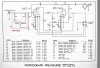
Phono Preamp for 24B.
attachment.php


If you look at the tuner section of the schematic in the lower right corner you'll see J-12 which I presume is for the 24 and 24A. But the layout is identical to the 24B preamp plug. Look at pin 2, then folow that lead around to the left where a tag drops off to the 6 pin. That lead goes to pin 1 which is not connected to the preamp at all. Am I missing something or is the return from pin 2 thru the lead to pin 9 on the 12 lead plug into the amp?
 

Attachments

  • ScreenHunter_87 Oct. 27 17.31.jpg
    ScreenHunter_87 Oct. 27 17.31.jpg
    108 KB · Views: 42
Larry -- The heater for the external preamp operates off of -- you guessed it -- DC power from the power supply.

Follow the circuit this way:

1. The ground side of the 12AT7 heater is pin 5 of the tube socket, which is grounded inside the preamp.

2. The ground lead of the preamp plug is pin 3. In the preamp power socket on the compressor chassis, pin 3 follows over to pin 3 of the 6 pin plug. In the main tuner chassis, pin 3 of the 6 pin socket is grounded, so the ground integrity is established.

3. The 12AT7 is operating in 12.6 volt mode. The hot pin of the heater at the 12AT7 tube socket is pin 4, which connects to pin 2 of the preamp power plug. In the preamp power socket on the compressor chassis, pin 2 follows over to pin 2 of the 6 pin plug.

4. In the tuner chassis, pin 2 of the 6 pin plug carries over to pin 9 of the main interconnect between the amplifier/power supply, and the tuner chassis.

5. In the amplifier/power supply chassis, pin 9 connects to the junction where R27 connects to the CT of the HV winding in the power transformer.

Theory: The entire system draws ALL power across R27, a 150 10 watt resistor. If no phono preamp is connected, that's then end of the tale. But if it is connected, R27 is sized so that when the 150 ma 12.6 volt configuration of the 12AT7 heater is connected across it, a voltage drop of about 12 vdc occurs, lighting the heater in the phono preamp with DC power.

If the heater is not lighting, either integrity has been lost in the ground circuit to the phono preamp, or, integrity has been lost from the positive side of the heater back to the junction point at R27.

Obviously, this design requires ALL tubes to be in place for there to be enough current draw to light the 12AT7 heater. And of course, R27 must be of the correct value and present.

With this understanding then, its a matter of finding where the integrity is lost. At the very least, check the voltage at the junction of R27 and HV CT to ground. It will likely be GREATER than -12 vdc because the heater is not operating to draw the voltage across that resistor down to that value. In essence then, the heater of the 12AT7 phono preamp tube is connected in parallel with R27.

I hope this helps!

Dave
 
Last edited:
Back
Top Bottom