• The move to the new server is done. There are some software and database maintenance updates in process. This has us passing the hat around to help out. We appreciate any donations. Seriously, even a dollar helps. The payment page may be found here - https://www.audiokarma.org/support.html

Possible Model 24 Rehab

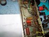
Did rewiring of the indicator lamps y'day. Rotten wire insulation.

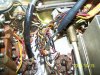
The bare wire on #3 is a remnant of the Negative lead. POSITIVE Lead is Heatshrunk from the Center TIP back two inches.
attachment.php


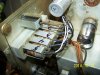
The positives all connect to different terminals on these two strips. The Negatives used to terminate to ground points behind the ROTARY in the left corner. Had to unmount the Turret board, and the Rotary to move it back far enough to clip, but not enough room for an iron or desoldering tool Unless I removed everything from the side wall to allow the rotary to move back more than a 1/2". AND There is a 30uf/250V Cancap in that corner which you can't see. I managed to tuck a 33uf 400V Pencil type cap in and replaced the can with that between the wiring and the chassis shell. It's tight in there and the cap is not going anywhere.
attachment.php


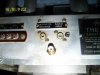
As the condition of the RCA jacks are poor, We decided to renew all of them (7). This shows the TV connection (which was one of those single screw on connectors) with a replacement RCA Jack. I only had one, so thi is where it went for DEMO purposes. I'll get one of those DYMO label makers and make some labels for all of them instead of the Sharpie marks.
attachment.php
 

Attachments

  • 100_4624.jpg
    100_4624.jpg
    93.2 KB · Views: 66
  • 100_4623.jpg
    100_4623.jpg
    132.2 KB · Views: 66
  • 100_4628.jpg
    100_4628.jpg
    79.3 KB · Views: 65
The BIG MOUSER order arrived about 3pm. So far the AMP is done.

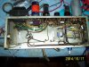
BEFORE: Note the EROFOILS sitting in there BEFORE installation. The output Coupling caps are listed as .1uf 800V. All of the wax caps are 600V. As I had the EROFOILS (.1uf 1KV) I used them.
attachment.php


AFTER: The POSITIVE POSTS in the CAN CAPS were fairly well corroded to the point where 3 of 5 broke off with minimal force while dewiring them. I was going to stuff them, but said the hell with it and went with Terminal strips. Note also the difference in the size of the 50uf/50 Axial and the 25uf/25v axial on the left side and the 47uf/50 and 27uf 25V replacements. That's 63 years of technology for ya! The two gray rectangular caps up top are the .1uf 300VAC (1KVDC) X-Y2 rated safety caps. I installed 2 CL-60's(10ohm 5A) at the input of the cord in the lower right hand corner. (The switches are on the tuner). The input fuse is rated for 5A as noted on the schematic. There's a Hell of a lot of Juice going into this beast! 525w@105V to 600W@120V rated.
attachment.php


Next installment is the Expander and compressor (I'll leave the tuner for last!)

Larry
 

Attachments

  • 100_4630.jpg
    100_4630.jpg
    116.1 KB · Views: 76
That went faster than I thought it would take.

The only thing's left on the Expander, Compressor are the RCA JACK replacements, and new tubes. Some time next week.

Dynamic Volume Expander BEFORE All caps were taken back to the actual connection, old wire removed, connection de-soldered,

attachment.php


Dynamic Volume Expander AFTERnew lead wrapped on, and re-soldered. The 2 section Can cap was De-Soldered, Terminal strip soldered to one of the ground points. Ground was ohm'ed out to ZERO OHMS. The nthe new Radial caps were soldered to the outer terminals with the center being Negative.

attachment.php


Dynamic Noise SuppressorAFTER (I forgot to take a before...D'OH!!) Caps were taken off the turrets, wires removed, turrets desoldered, and redone. The DUAL CAN CAP sections were actually 2 40uf paralleled to make 80uf. I put the 47uf's on a terminal strip, soldered it to the Can cap mount and chassis (Negative). Ohm'ed to 0.01ohms. Wire brushed it a little and got it down to 0.00 ohms. As the terminal strip is up against the cover I taped it with Cloth electricians tape, and covered with Vinyl Electricians tape so there is very little if any chance of shorting to chassis. Just incase anyone notices I did notice the wax cap above the rotary switch and replaced it while posting this post. So it's done.

attachment.php


Time to take a break, eat, and crash! Probably more Saturday late. Tomorrow's Honey-Do day and I've got 3 yards to cut, if the weather holds off.
 

Attachments

  • 100_4632.jpg
    100_4632.jpg
    99.7 KB · Views: 55
  • 100_4633.jpg
    100_4633.jpg
    119 KB · Views: 55
  • 100_4634.jpg
    100_4634.jpg
    127.8 KB · Views: 56
Nice work Larry. It makes the quickie refresh on this Bogen tuner look like child's play. I think my Scott 800B was a bit worse to overhaul, if only for the metal bathtub caps. I actually rebuilt all of the damn things. If I ever mess with bathtub caps again, they go in the trash and I'm bolting in terminal strips.
 
Thanks Thain. The Tuner has (last I counted) close to 30 caps all over, about 10 are in the tuner box and in really tight quarters(that's gonna be FUN!).

Off topic. I think the Sherwood tuner might work from what I've tested so far (trannies, and a few caps). Both it and the Eico sat in a shed a hell of a longtime. Surface rust on the top of the chassis. I may take them down to bare metal on top, wirebrush, then some of that rust turn paint, and then paint chassis black. The case on the sherwood cleaned up really nice too.

Ok back to your regularly scheduled thread.
 
Didn't have time to do anything except clean up the room. So I put some shelves up, and then took and did a count of the parts I've replaced so far.

40 caps.
3 motor mounts
1 RCA jack to replace the screw on TV plug/jack.
8 tubes that I had in stock. (not counting the LOCTALS).

All this is from the Phono, Phono preamp, Noise Suppressor, Volume expander, and the AMP. Nothing on the Tuner has been replaced. But between the caps and the tubes, the parts count will probably double.

Not included are the Inrush Limiters.

attachment.php
 

Attachments

  • 100_4637.jpg
    100_4637.jpg
    92.6 KB · Views: 52
I finally got some time to recap the tuner. WHAT A PITA! Some of the 30 caps were buried 3-4 layers down and with the way I'm doing it (socket pin to socket pins, No "J" connectors except to lengthen the leads then heatshrink), it was TIME consuming.

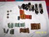
And a DRASTICALLY DIFFERENT LOOK underneath.

1949 Capacitor TECHOLOGY.
attachment.php


2014 Capacitor TECHNOLOGY
attachment.php


Caps Changed out today. 27 replaced, plus 3 can cap sections replaced underneath.
attachment.php


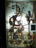
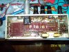
There is a 5koHm 5W resistor in the FM Tuning indicator circuit that went open and cracked open it's shell. In the pics it's right above the Date. One pic it's plain, the other it's marked. So I've got a couple of them on order.

Once i get those installed, the NEW RCA Jacks in, and the tubes I'll be ready to bring it up on the DBT/VARIAC REAL SLOW!

Probably next weekend. Rounding Third, and making a run for Home!

Larry
 

Attachments

  • 100_4640.jpg
    100_4640.jpg
    87.2 KB · Views: 54
  • 100_4639.jpg
    100_4639.jpg
    152.5 KB · Views: 54
Looks nice. Also nice pile of "Sealdtite" caps. Always thought they looked neat, but they ain't much good except for decoration. Some folks might buy them to re-stuff but I'm not that dedicated.
 
Great job Larry, sending you my Sansui 8080 DB for recap..lol

Any series but the x0x0's. They aren't that hard to recap but the traces are so fragile all it takes for them to flake off and curl up is waving a COLD Soldering Iron withing 200ft. You got an extra F-2436 board laying around so I can get my 9090 running?:D

Thain; A couple of those Sealtite caps had actually split lengthwise, and a couple actually boke in 1/2 when I cut the leads off. Good thing I DIDN'T try to power it up 1st.

Dave; Thanks. I'm trying to make each one I do a little better than the last one, technique wise. This one was a challenge as it's split among 5 chassis'.
 
Last edited:
Any series but the x0x0's. They aren't that hard to recap but the traces are so fragile all it takes for them to flake off and curl up is waving a COLD Soldering Iron withing 200ft. You got an extra F-2436 board laying around so I can get my 9090 running?:D

I think that's a Sansui thing. I had issues with the traces in my 3000A...coupled with the fact that in that series, they didn't just solder the components in place and trim the leads - they folded everything over down the traces, and soldered along the whole length of the leads! What a PITA. Took about 3x as long to unsolder the parts as it normally would.
 
I think that's a Sansui thing. I had issues with the traces in my 3000A...coupled with the fact that in that series, they didn't just solder the components in place and trim the leads - they folded everything over down the traces, and soldered along the whole length of the leads! What a PITA. Took about 3x as long to unsolder the parts as it normally would.

Agreed. All of my 2000's (2K, 2KA, 2KX) all have the leads folded over, but the traces on them are thick as hell. Maybe they switched board types between the series? But I do know the boards on my 9090 are so thin, I didn't have a trace that didn't lift. And most of them on the amp board, ended up re-wiring the board, and it still don't work. I just might give it up for parts (maybe).
 
I got the RCA Jacks from Mouser the other night, and replaced all the old RCA's and the one Screw in TV JACK.

Then finished up rebuilding the remaining old metal encased coax interconnects. There was an UNKNOWN cable coiled up. Finally figured out what it was for. It's for the Muting switch from the turntable to the Preamp. So I remounted it and connected it up. New Power cords for the AMP and the Expander finished it out. Finally I placed the components on the shelves and wired them up as they would be in the GEORGIAN CABINET
I intentionally left the interconnects a little long.

The only thing left before initial power up is one Power resistor enroute, and me getting the tubes tomorrow. Should know it's condition this weekend.

Left to Right..TOP SHELF..Expander, Tuner/Preamp, Noise Suppressor, Preamp

Next Shelf....Amp, Turntable.

attachment.php


attachment.php


attachment.php


attachment.php


attachment.php


The power plug marked "C" is for the turntable.
attachment.php


Larry
 

Attachments

  • 100_4648.jpg
    100_4648.jpg
    89.9 KB · Views: 48
  • 100_4649.jpg
    100_4649.jpg
    58.9 KB · Views: 46
  • 100_4650.jpg
    100_4650.jpg
    69.8 KB · Views: 45
  • 100_4651.jpg
    100_4651.jpg
    65.1 KB · Views: 46
  • 100_4652.jpg
    100_4652.jpg
    66.9 KB · Views: 47
  • 100_4653.jpg
    100_4653.jpg
    71.5 KB · Views: 46
Got a bagful of LOCTAL Tubes from Ohighway. Unfortunately he didn't have a 7c7, so i ordered one and a 0A2 (neither of the ones he pulled were showing real good on my tester) from AES.

The 5kohm 5W resistor came in tonight and installed. So I'm waiting on 2 tubes before I power it up. I suppose I could take a shot with the old tubes in there but that 7C7 was super weak (15 on scale of 100). I put it on the tester with the heaters @ 7.5V to try to rejuvenate it enough to try and test the unit on the DBT and Variac. We'll see in the morning.
 
I pulled the tube out of the tester and let it cool for a 1/2 hour this morning and then put it back in the tester and fired it up. NO Shorts, and emissions went from 15 to about 40 and held a minute with no change. So I'm gonna try the 7c7 in it today. Hopefully there is enough to at least prove out the system, before the new tubes arrive.

Crossing fingers. Now to break out the DBT and variac.

The assembled chassis' sitting on top of my '51 CORONET (WR-11 WARWICK) with the R-3 receiver. The cabinet for the '49 is the GEORGIAN which is about 1' wider than the Warwick Cabinet. The basic orientation of the individual chassis (except the amp) is correct left to right. The phono preamp sits in a hanger above the noise suppressor("N" Knob), then the tuner, then the Expander("E" Knob). The amplifier sits below the tuner, and the turntable sits to the left of the tuner chassis, basically the same as the WARWICK. I wish I had more and better pictures of a GEORGIAN. Buglegirl has a 51 or 52 GEORGIAN with an R3 in it and it's HUGE comparitively.

attachment.php


I'll pull out the R-3 later and take a picture of it next to the Model 24 for comparision.


Larry
 

Attachments

  • 100_4654.jpg
    100_4654.jpg
    97 KB · Views: 39
Last edited:
that is definitely a beast. Now you need a Scott 800B to restore so you have worked on both of the early big boys. The Scotts only use 2 chassis though. They also don't have that noise supressor or the range expander, so all things being equal that Fisher has more sound-related features. The Scott has that way cool motorized tuning preset deal going for it.
 
I just powered it up, with antenna's and a speaker to it. NOTHING!!!!! IN ANY MODE, NO FM , NO AM, NO SW (The Eye tube does NOT React to tuning up and down the dial.)

With the volume all the way up and my ear 2-3" away from the speaker (Minimus 7) I get a very slight hum.

Touch and hover test of the tubes show that V8 and V9 are STONE COLD and the filaments are not glowing! No heater voltage? I haven't opened them back up yet, so i don't know what's going on.

Now the FUN with DMM begins!

Larry
 
HOUSTON, WE HAVE LIFTOFF, The Clock is RUNNING!!!

Well, I cleaned all the tube sockets with pipe cleaners and DeOxit, and tightened all the socket pins. For LOCTAL TUBES there were a shitload of loose pins.

IT"S AAAAAALLLLLLIIIIIIIIVVVVVVVVVEEEEEEEEEEEEEEEEEEEEEEE!( The Gene Wilder Version). Critical list, but it's alive, But IMPROVING!!!

1.) PHONO PREAMP is NOT working. No Heater Voltage to the 12at7, but all the wiring ohms out good. (Gotta dig deeper).

1a.) I took a generic Stereo phono preamp and hooked it up that way and it sounds pretty good.

2.) Expander and compressor work. But not as well as i expected them to. But they do work.

3.) TUNER.

3a.) SHORTWAVE works. I have a 6ft piece of wire on the AM antenna side. Pretty decent reception.

3b). AM Reception is fairly strong on the lower 1/2 of the band and fades out to almost nothing on the upper end. The 1KW station 4 miles away from me at 1590kc is so weak as to defy logic.

3c.) FM...INITIALLY NOTHING! BIG FAT ZERO! But afterwards I went thru and checking tube pins and found the 6J6 and 6AG5 were reversed. reversed them and have VERY NICE FM!!!

So AM needs some work, and the phono preamp needs work.

DAMN, I'm stoked!! 90 second .MOV here for those who feel the need..................... https://www.hightail.com/download/UlRTQmtjckk5NVVYRHRVag
 
Back
Top Bottom