• The move to the new server is done. There are some software and database maintenance updates in process. This has us passing the hat around to help out. We appreciate any donations. Seriously, even a dollar helps. The payment page may be found here - https://www.audiokarma.org/support.html

Problems With Sansui G9000 - Cooked?

Any trustworthy place you guys deal with to purchase new power transistors such as these? I know there's a lot of knock-off crap out there, and would like to avoid it.
 
@specialone53: You say these are quite common.. Where would I find a replacement?

I've searched for the last hour, and I cant find even a cheap counterfeit. I'm beginning to get the feeling that these things don't exist anymore....
 
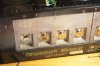
The output transistors are easily accessed by unscrewing the heatsink off the back (i think there are 8 screws for each channel) and then you can unscrew the transistors and pull them out of the sockets. No need to unwrap anything. I have attached a picture of how it looks with the heatsink off.

Use onsemi MJ21193G and MJ21194G for the output transistors. Replace all of the ones for that channel even if only 1 tests bad the others are not far behind if something blew in there.
 

Attachments

  • DSC_0103.jpg
    DSC_0103.jpg
    61.8 KB · Views: 35
WOW... I feel a little dumb... ehh, live and learn, right? Now I know why they looked odd to me, I was looking at the back of the sockets.. Is there a procedure or a list of things I should check to see if this was the cause or effect of failure? as I'm understanding it, these transistors shorted internally, and cause the driver running them to cook... Am I correct or is it the other way around?
 
I think the main reason these output (and driver) transistors go is that someone had a shorted speaker or somehow shorted the outputs. In your case it could be a million different things, although it seems like the usual culprit was not the cause here. I would bet in your case that one of the small potentiometers for setting the bias has opened up which caused runaway bias, or there are a bunch of small metal film resistors on the driver card that go hi-Z after the years or heat. Maybe the dust had something conductive in it (don't laugh, I once repaired an amp with 2 lbs of glitter inside it. someone must have dropped a container of it on the vent). Anyway do transistor test on the outputs, drivers (the 2 TO-220s at the bottom of the driver card) and those resistors between them. You might have to pull some of the resistors off the board to get a correct reading. I can guarantee you will find more bad components.
 
Well, This unit does live in a welding fabrication shop, plenty of conductive grinding dust in the air I'm sure... The TO-220's all checked out ok, and already replaced a few resistors, now I'm thinking your pot theory may have some gravity.. I'll pull those and check them as well. I also have read that after all is said and done, I may need to set the bias for the driver.. thoughts?
 
The bias is super easy to adust once the fault is repaired. You will need a few things to make this successful. A dim bulb tester (there are a bunch of posts in this forum and elsewhere online how to make one), and the service manual, which you may already have. To test the bias pot you will probably have to unsolder it from the board and test the resistance with your meter. The wiper lead should be obvious from looking at it, and there should be a fixed resistance between the other two leads. I am blanking as to the resistance it should be, and the service manual is on my other computer. Checking that pot is a good start. Don't adjust it though, just check it. I proactively replace all the small pots when I work on something, and generally use 25 turns Bourns units which are very easy to do fine adjustments to get it perfect. The easiest way is to set it to the value of the old one using your meter, then put it in, and it should be close enough that the receiver will start and not blow any transistors and then you can dial it in perfect.

Also don't adjust the bias while the receiver is plugged into the dim bulb tester. It will be waaay to high once plugged straight into the wall.
 
The dim bulb tester will protect the output transistors from blowing again if there is still a problem in the output or driver section. at $6 a piece X 8, spending $10 at the hardware store for parts to build a DBT is worth the $48 of output transistors in there. It will be bright initially while the main filter caps charge, for maybe 2-4 sec, then dim to where the bulb is hardly lit or completely out. If it doesnt dim at all after 5 sec, there is still a short in there, turn the receiver off. It won't detect all problems in there, but will show the kind of problems that will blow a mains fuse.

Don't worry so much about adjustments yet, we need to repair the faults first, then adjustments come later.
 
OK, Tonight I will put together a dim bulb tester, I believe I have a spare porcelain socket around that would work nicely. Any suggestion as to the wattage I should use?
 
DBT's are only good for testing the p.s. on SS equipment. (unless the rectifier is on the main board along with the outputs the outputs IMO should have not been soldering in yet.) If the PS with rectifier is on it's own board, disconnect the power lead.
 
DBT's are only good for testing the p.s. on SS equipment. (unless the rectifier is on the main board along with the outputs the outputs IMO should have not been soldering in yet.) If the PS with rectifier is on it's own board, disconnect the power lead.

I don't quite understand your logic there.

A DBT used in conjunction with a variac is a tool we techs use to prevent excessive current/additional failures in equipment that may have comprimised components whether it is tube or transistor based.
 
I read somewhere that I may have to replace the Mica pads under the transistors? is this only when they are damaged? or all the time? And for the bias adjustment, the manual says measure from "TP Terminal (+) (-)". I cant really find any other refrence to where these terminals are. My guess is There's a picture on page 17 in the manual and on the far left and far right of the heat sink there are, what appear to be test leads with (+) and (-) next to them.
 
I read somewhere that I may have to replace the Mica pads under the transistors? is this only when they are damaged? or all the time? And for the bias adjustment, the manual says measure from "TP Terminal (+) (-)". I cant really find any other refrence to where these terminals are. My guess is There's a picture on page 17 in the manual and on the far left and far right of the heat sink there are, what appear to be test leads with (+) and (-) next to them.

My guess is that if you're that unfamilier with electrical troublshooting and the need for replacement parts, simply find a qualified serviced technician to do the job.

I'm sure you've seen the warning labels on equipment that read:
"No user serviceable parts inside - leave servicing to qualified service personel".
 
I could, Or I could learn Something.. If this manual didnt leave so much to the imagination I wouldn't be asking about the test points. Was pretty sure these kinds of questions are acceptable in the DIY section.
 
I could, Or I could learn Something.. If this manual didnt leave so much to the imagination I wouldn't be asking about the test points. Was pretty sure these kinds of questions are acceptable in the DIY section.

The writers of Service Manuals conveyed the information clearly for those trained in troubleshooting procedures, and having a solid background in the service industry.
Obviously they're confusing to the diy tinkerer with no knowledge of such things.
And this cannot be fully replaced by online corrospondence, in part because a lot of this information highway contains misinformation from other tinkerers with no formal background either. - AKA the blind leading the blind.

I certainly know this for fact, having had formal training, and reading the amusing blogs all over of "it might be this or thats".

Success "online" is basically like a board game of sorts - ya take your chances
and hope for the best.
And of course the common replies to this are most always in defense of the internet and its followers, which doesn't hold much water anyway.
 
ok, so im on my own. kind of a nice unit to blow up in training, but if i have to smoke this bitch... Here it goes. Ill be sure to post pictures of it's smoldering corpse afterwards.
 
Back
Top Bottom
