• The move to the new server is done. There are some software and database maintenance updates in process. This has us passing the hat around to help out. We appreciate any donations. Seriously, even a dollar helps. The payment page may be found here - https://www.audiokarma.org/support.html

Project: Yamaha CR-820 (Rebuild)

ZHFaKR3fNohAZLnK6SgMP0VjCFFapsdZCtjyTYSKB9vewEPjTQSancqyKCVNl9Kc94ENW-FZAjhlLp8C-qjtFjNQsSYeqjVuOAM9bGY_7R5RrPX5RNi9zam8TK-zeTNGEBofQvyV0g=w1175-h881-no


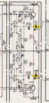
Went back in and changed the LED resistor setup.... timing is right now (no sneaker on the gym floor sound on turn off).

Went ahead and changed the dial LED illumination to green. Tell you what = nice looking and sounding set.

LGDmfj0YvBz0Ah_sh1MGuxRWVlkUEISxaGulUSz0hUY1UmDAUpllcM01IolY9L3FQdccodS4juBzfVhNotVkzJu9W3xNL4GVK6yhLZUMiQP27Gnbb-8OvcnvZK_6phnx_bDw-O9nyw=w1175-h881-no


EKGJyMzk9CsLT6mfFukH9t6MLoCFf7LnVavLQBc3UHMOsmon--SbeRl3vcMQcrwqYBUm9wcqsblA4u94JErgIPPAv0GmjXDKl09Gm-xBhF75gZZipx0rC6L-bvVBGQxFuDkY5YVYkg=w661-h881-no
ZHFaKR3fNohAZLnK6SgMP0VjCFFapsdZCtjyTYSKB9vewEPjTQSancqyKCVNl9Kc94ENW-FZAjhlLp8C-qjtFjNQsSYeqjVuOAM9bGY_7R5RrPX5RNi9zam8TK-zeTNGEBofQvyV0g=w1175-h881-no


Went back in and changed the LED resistor setup.... timing is right now (no sneaker on the gym floor sound on turn off).

Went ahead and changed the dial LED illumination to green. Tell you what = nice looking and sounding set.

LGDmfj0YvBz0Ah_sh1MGuxRWVlkUEISxaGulUSz0hUY1UmDAUpllcM01IolY9L3FQdccodS4juBzfVhNotVkzJu9W3xNL4GVK6yhLZUMiQP27Gnbb-8OvcnvZK_6phnx_bDw-O9nyw=w1175-h881-no


EKGJyMzk9CsLT6mfFukH9t6MLoCFf7LnVavLQBc3UHMOsmon--SbeRl3vcMQcrwqYBUm9wcqsblA4u94JErgIPPAv0GmjXDKl09Gm-xBhF75gZZipx0rC6L-bvVBGQxFuDkY5YVYkg=w661-h881-no
I hope you don’t mind me reviving an old thread. How did you arrange the leds to resolve the timing issue? I experience a new shutdown pop since I’ve converted to led.
 
I hope you don’t mind me reviving an old thread. How did you arrange the leds to resolve the timing issue? I experience a new shutdown pop since I’ve converted to led.
Did you try the arrangement mentioned in post #26 of this thread?
 
The two 470 Ohm 1 Watt resistors added in parallel with the LED pairs will run very hot. I would increase the power rating to 3 Watts for each 470 Ohm resistor.
 
I am planning to re-do my cr-820 using this thread as a guide. I've only used kits before so I thought it would be fun to spec out all the components myself. I'm trying to modernize the list of caps and transistors to what's available today and wondered when it comes to electrolytic caps, is there a specific line or series from the reputable brands like Nichicon, Rubycon, Panasonic and Chemi Con that I should be targeting or is anything pretty much ok? I noticed the lower voltage 10uF caps seem to be obsolete from Nichicon and Rubycon so those prices have crept up a little compared to the active parts. I'm trying to do this all in one order and am afraid if I grab all 50v that in some cases they might be too wide etc. Any advice for trying to put together an order like this?

 
I am planning to re-do my cr-820 using this thread as a guide. I've only used kits before so I thought it would be fun to spec out all the components myself. I'm trying to modernize the list of caps and transistors to what's available today and wondered when it comes to electrolytic caps, is there a specific line or series from the reputable brands like Nichicon, Rubycon, Panasonic and Chemi Con that I should be targeting or is anything pretty much ok? I noticed the lower voltage 10uF caps seem to be obsolete from Nichicon and Rubycon so those prices have crept up a little compared to the active parts. I'm trying to do this all in one order and am afraid if I grab all 50v that in some cases they might be too wide etc. Any advice for trying to put together an order like this?
For the power supply caps most people recommend those with low ESR values and high ripple currents. With Nichicon these are UPM and UPW iirc off the top of my head. As far as signal path, Nichicon has an audio series, but like you mentioned, I've noticed a lot of the smaller values are becoming obsolete, especially in this series. You should be fine to go up voltage, just not capacitance.
 
I see low esr high ripple recommended for signal path too so that's why I am having trouble choosing. And is like the lifetime at 105C just as important? Really is anything from these companies just going to be good or better than what was in there new from the factory?
 
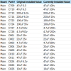
So I might be nuts but I decided to pull all 88 electrolytics in this thing, measure them, identify each one's ID in the schematic (their IDs aren't marked on the boards in most cases and not labeled in the service manual) and log them into a spreadsheet. I also took pictures and labeled each location with a photo editor. I then took this data and compared it with @Super Noob's info from the beginning of this thread as a sanity check and there's a few discrepencies where he found different values for items than what was in the schematic. I didn't have those issues aside from a few 100uF caps that were 10v instead of the 6.3 in the schematic. Also there were two ELNA caps in the phono stage which were odd considering no other ELNAs anywhere. I don't think this unit was untouched though. There's some clear non-original solder joints here and there.

Anyway I took all @Super Noob's recommendations for upgrades and parts and dealt with the fact that in general, where possible I wanted to use active parts but I did deviate from this a bit. I wound up speccing Wima film caps for everything 2.2uF and under. Everything in the signal path over 2.2uF either got Nichicon UDB or UES bi-polar electrolytics and everything not in the signal path got Nichicon UVZ polarized electrolytics. This is my first time not using a "kit" so I hope I made the correct choices. Once everything is installed and working I hope to organize everything into a pdf and upload it to the DB. In the meantime I'm happy to share this updated BOM and pictures with anyone, just understand it's not vetted even by me yet ;)
 
Working on this I didn't check the 2.2uF WIMA caps I bought but they have the short pc pin leads and 15mm leg width and I need to get them into like 3mm width holes. Is it ok to solder some leads to these pins to make it work with maybe some shrink wrap to elimate any potential shorts or will this basically defeat the whole purpose of using the film cap and I should just get some audio grade electrolytics like I did for the larger values in the signal path? It also looks like these only come into play when the high filter is enabled? Considering just putting the old caps back if that's the case:

1772212605709.png
 
Last edited:
I try to get parts with proper fit in the application and give that a high priority. A film capacitor with 5mm lead spacing should fit it the board. Mouser has Kemet capacitors, 80-R82CC4220DQ70M at 2.2uF 50V. DigiKey has a marketplace listing for WIMA MKS2 capacitors but you must buy ten at $3 each. On ebay Affinity for Artifacts has 2.2uF WIMA capacitors at ten for $15. In all cases add tax and shipping charges to get the parts to your door.
 
I try to get parts with proper fit in the application and give that a high priority. A film capacitor with 5mm lead spacing should fit it the board. Mouser has Kemet capacitors, 80-R82CC4220DQ70M at 2.2uF 50V. DigiKey has a marketplace listing for WIMA MKS2 capacitors but you must buy ten at $3 each. On ebay Affinity for Artifacts has 2.2uF WIMA capacitors at ten for $15. In all cases add tax and shipping charges to get the parts to your door.
Right I was hoping to not have to re-buy anything and incur another shipping cost. Maybe I'll put the old ones back and in a future parts order grab some different ones. How do people generally regard the Kemet caps?
 
Let me know if I should make my own thread for this but after removing 88 caps, ordering all new ones and then installing them all alongside the two amp board VRs and the 8 amp board driver transistors, I had no magic smoke. A miracle. One problem though is that loudness is super harsh, I'm wondering if where I deviated from @Super Noob 's plan has got me into trouble. This is the list of caps he kept polarized but I opted to change to bipolar as they were in the signal path so I grabbed some of those nice green Nichicon UES caps and replaced them. They're mostly in the tone board but a few are in the amp board too. Is it not always ok to replace polarized caps with bipolars in the signal path?
1772395008416.png
 
I put coil capacitors up to 2.2uF in the signal path and bipolar elements for larger capacities. I maintain the voltage or go an order of magnitude higher. Coil capacitors Wima or Panasonic and bipolar elements Nichicon.
Pavel ;)
 
I put coil capacitors up to 2.2uF in the signal path and bipolar elements for larger capacities. I maintain the voltage or go an order of magnitude higher. Coil capacitors Wima or Panasonic and bipolar elements Nichicon.
Pavel ;)
yeah that's what I did here, all the UES caps are Nichicon audio bi-polar elecrolytics.
 
Last edited:
I removed all the of bipolar electrolytics in the tone and amp boards and replaced with them with the original or new polarized caps with no change. One thing I did notice before doing this is when I touched the top of bipolars I installed in C709 and C710 I could hear some attenuation of the signal and increased hum.

Is it ever a problem if you way overshoot the voltage rating with a replacement? For example...

1772474191726.png

And even though I can hearly clear a problem with speakers or headphones with music, if I send a 1 volt, 1kHz sine or square wave through the aux input, it looks totally normal at the speaker terminals with loudness set to flat. With loudness set to half, it sounds pretty normal.
 
Last edited:
Might be some of the known noisy transistors in there.

like the 2SC458

 
Back
Top Bottom