• The move to the new server is done. There are some software and database maintenance updates in process. This has us passing the hat around to help out. We appreciate any donations. Seriously, even a dollar helps. The payment page may be found here - https://www.audiokarma.org/support.html

Protection mode.... sansui au-717

Jeff Howard

New Member
Spent several months recapping my late grandfather's sansui au-717 and after turning it on it is staying in the blinking light mode or protection mode.
Getting 0 volts in both speaker terminals for dc offset.
Getting almost 0v on f-2721 for bias current voltage.
But for f-2722 I am getting 2.5VDC for bias voltage. Adjusting VR03 gives no improvement and it stays at 2.5vdc.
Would a damaged varistor cause this issue? I was unfamiliar with the function of a varistor before installing them and trying to set the resistance before installing them. (Not realizing it's not a potentiometer) so I may have over rotated the dial on the varistor and damaged it.

Any advice?
Thanks in advance
 
Register to hide this ad
You won't get anything at the speaker terminals if the relay isn't clicking in. If DC offset it too high, it won't come out of protection. You'll have to measure it at a point before the relay. I get the feeling you've never worked on one of these. If that is the case, it might be better to find someone local who can put eyes on it to see what is going on. Nobody can see what you have none, or haven't done.
Which boards did you recap? Which ones didn't you do? Did it work before you started? Are any caps in backwards? (yes it happens to many of us) What all did you "replace"? Are all the wires connected correctly? Was all the old glue removed and all the corroded parts replaced? Did you take photos of anything?
 
You won't get anything at the speaker terminals if the relay isn't clicking in. If DC offset it too high, it won't come out of protection. You'll have to measure it at a point before the relay. I get the feeling you've never worked on one of these. If that is the case, it might be better to find someone local who can put eyes on it to see what is going on. Nobody can see what you have none, or haven't done.
Which boards did you recap? Which ones didn't you do? Did it work before you started? Are any caps in backwards? (yes it happens to many of us) What all did you "replace"? Are all the wires connected correctly? Was all the old glue removed and all the corroded parts replaced? Did you take photos of anything?
Yes it was my first attempt at restoring an amp, I have some experience with audio electronics but I figured you have to try to learn. I replaced all electrolytics on f-2663, both driver boards and the tone board. I replaced the relay on f-2663 and all of the zener diodes. It didnt work before I started but it I did have it working at one time. I went on the assumption that a capacitor had likely failed, (should have troubleshot the original problem probably). I also replaced the 4 main caps with gold tunes.
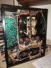
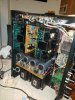
I attached some pictures maybe you can see something obvious. But, I will look into finding someone local who has some experience with these things.
 

Attachments

  • 20200131_203029.jpg
    20200131_203029.jpg
    81.6 KB · Views: 44
  • 20200131_213812.jpg
    20200131_213812.jpg
    86.5 KB · Views: 42
  • 20200131_213819.jpg
    20200131_213819.jpg
    77.6 KB · Views: 42
Yes it was my first attempt at restoring an amp, I have some experience with audio electronics but I figured you have to try to learn. I replaced all electrolytics on f-2663, both driver boards and the tone board. I replaced the relay on f-2663 and all of the zener diodes. It didnt work before I started but it I did have it working at one time. I went on the assumption that a capacitor had likely failed, (should have troubleshot the original problem probably). I also replaced the 4 main caps with gold tunes.
I attached some pictures maybe you can see something obvious. But, I will look into finding someone local who has some experience with these things.
 
Yes it was my first attempt at restoring an amp, I have some experience with audio electronics but I figured you have to try to learn. I replaced all electrolytics on f-2663, both driver boards and the tone board. I replaced the relay on f-2663 and all of the zener diodes. It didnt work before I started but it I did have it working at one time. I went on the assumption that a capacitor had likely failed, (should have troubleshot the original problem probably). I also replaced the 4 main caps with gold tunes.
I attached some pictures maybe you can see something obvious. But, I will look into finding someone local who has some experience with these things.
Can't see anything in a photo that small. Did you replace the VD1212 diodes in the EQ board (the board on the right side) with pairs of 1N4148? If so, the lower one is so close to the switch shaft it can short out against it.
 
Can't see anything in a photo that small. Did you replace the VD1212 diodes in the EQ board (the board on the right side) with pairs of 1N4148? If so, the lower one is so close to the switch shaft it can short out against it.
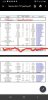
Yes I did. I've attached the list of components I replaced. I'll check and see if they're too close to the switch shaft. I can upload close pics of the boards once I disassemble it
 

Attachments

  • Screenshot_20200202-082840_Drive~2.jpg
    Screenshot_20200202-082840_Drive~2.jpg
    40.9 KB · Views: 21
  • Screenshot_20200202-082853_Drive.jpg
    Screenshot_20200202-082853_Drive.jpg
    30.4 KB · Views: 18
Yes I did. I've attached the list of components I replaced. I'll check and see if they're too close to the switch shaft. I can upload close pics of the boards once I disassemble it
Before you disassemble anything, just remove the bottom cover and look to see if that is touching the shaft. Once you remove anything you'll likely not be able to tell how close it is.
 
Do you have and use a DBT? (Dim Bulb Tester) If not, look it up and build one and use it with an *incandescent* bulb of 60W minimum, or up to 100W maximum depending on what you can find. It will save you from smoking anything and let you know if anything is drawing too much current.
 
Do you have and use a DBT? (Dim Bulb Tester) If not, look it up and build one and use it with an *incandescent* bulb of 60W minimum, or up to 100W maximum depending on what you can find. It will save you from smoking anything and let you know if anything is drawing too much current.
Can do. I'll check the current draw and the diode. Will update you what I find.
 
+1

There are fusistors on the amp boards that go high and mess with the bias.

There are also fusistors on the pre-amp board.

Other than glue rot on the power supply, fusistors are the biggest problem in those units.
I replaced all the fusistors and removed the glue the best I could. I also checked the replacement VD1212 diodes on the tone board as skywatcher recommended and they are not touching the switch shaft. I have yet to check the current draw of the unit
 
I replaced all the fusistors and removed the glue the best I could. I also checked the replacement VD1212 diodes on the tone board as skywatcher recommended and they are not touching the switch shaft. I have yet to check the current draw of the unit
Not the tone board, the EQ board. The board on the far right that is vertical with the 2 long switch shafts. I am assuming that is the one you meant. It is possible the DC offset is going to be way off since you replaced the trimmer pots. That would keep it from coming out of protection. Study the SM to locate where the speaker out comes from each amp, or to the regulated power supply/protection board before it gets to the speaker relay. Measure and adjust the DC offset there until the relay clicks in. After that you can use the speaker terminals to do the final tweaking. It's a bugger on this one with 2 trimmers, fine and course, to get with multi-turn pots the first time around. I personally only used a multiturn pot on the coarse adjustment (right pot) and a single turn for the fine adjustment (center pot). I was able to fine adjust with the multiturn without ever needing to touch the other one leaving it at the midway point.
 
It's probably going to be a good idea to pull each amp out to go over everything and compare them with each other to recheck your work. That means un-mounting the boards too to check all solder joints. And as "uninviting" as it sounds, the regulated power supply/protection board also might need to come back out. But do not power it back on without the DBT "safety net". The last thing you need to do is fry the input FET on each amp.
 
Not the tone board, the EQ board. The board on the far right that is vertical with the 2 long switch shafts. I am assuming that is the one you meant. It is possible the DC offset is going to be way off since you replaced the trimmer pots. That would keep it from coming out of protection. Study the SM to locate where the speaker out comes from each amp, or to the regulated power supply/protection board before it gets to the speaker relay. Measure and adjust the DC offset there until the relay clicks in. After that you can use the speaker terminals to do the final tweaking. It's a bugger on this one with 2 trimmers, fine and course, to get with multi-turn pots the first time around. I personally only used a multiturn pot on the coarse adjustment (right pot) and a single turn for the fine adjustment (center pot). I was able to fine adjust with the multiturn without ever needing to touch the other one leaving it at the midway point.
Oh Okay I understand. I will try this when I get off work. and yes I meant the EQ board my apologies. I'Il double check all the connections and then try adjusting the trimmer pots. But removing the power supply board would require me disconnecting it from the 4 main caps correct?
 
Oh Okay I understand. I will try this when I get off work. and yes I meant the EQ board my apologies. I'Il double check all the connections and then try adjusting the trimmer pots. But removing the power supply board would require me disconnecting it from the 4 main caps correct?
How did you get it out before to work on? Yes, the wiring on the bottom end needs to be desoldered from the board, and the mounting brackets removed to get it out in the open from the bottom. It's a pain, but the best way to do it. Take plenty of photos to have a wiring reference. regulated power board out.jpg You also need to be sure all the glue gets cleaned up, and *any* component that it touched replaced. The glue corrodes the leads. On this unit, I had to replace lots of diodes, resistors, and a couple of ceramic capacitors Note there is also a VD1212 that gets replaced.
 
Study the SM to locate where the speaker out comes from each amp, or to the regulated power supply/protection board before it gets to the speaker relay. Measure and adjust the DC offset there until the relay clicks in.
Conveniently, you can use either of the test point terminals (either '+' or '-') located in the top corner of each driver board, with your negative probe to chassis. These terminals are provided for ease of setting bias, but can be used to get DC offset 'in the ball park' to allow the relay to close. These connections should not be used for the final setting of DC offset, as neither of them is connected to exactly the right place to set or measure this properly. (the TP terminal '+' is connected to pin 9, and '-' is connected to pin 7 of the driver board, in other words across the 2 emitter resistors - for setting the bias - with one meter probe on each TP terminal for doing this adjustment).
 
Last edited:
Conveniently, you can use either of the test point terminals (either '+' or '-') located in the top corner of each driver board, with your negative probe to chassis. These terminals are provided for ease of setting bias, but can be used to get DC offset 'in the ball park' to allow the relay to close. These connections should not be used for the final setting of DC offset, as neither of them is connected to exactly the right place to set or measure this properly.
How convenient is that? :thumbsup:
 
Conveniently, you can use either of the test point terminals (either '+' or '-') located in the top corner of each driver board, with your negative probe to chassis. These terminals are provided for ease of setting bias, but can be used to get DC offset 'in the ball park' to allow the relay to close. These connections should not be used for the final setting of DC offset, as neither of them is connected to exactly the right place to set or measure this properly. (the TP terminal '+' is connected to pin 9, and '-' is connected to pin 7 of the driver board, in other words across the 2 emitter resistors - for setting the bias - with one meter probe on each TP terminal for doing this adjustment).
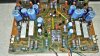
Is this correct John?
 

Attachments

  • DC Offset before relay.jpg
    DC Offset before relay.jpg
    105.3 KB · Views: 47
Back
Top Bottom