• The move to the new server is done. There are some software and database maintenance updates in process. This has us passing the hat around to help out. We appreciate any donations. Seriously, even a dollar helps. The payment page may be found here - https://www.audiokarma.org/support.html

Put a capacitor in backwards and it fixes the problem???!!!

rudkinst

Active Member
Hello. Pretty much a newbie just getting into fixing up older equipment. Playing with an old Rotel Rx150A. 12wpc I think, very simple. Left channel is good, right is fuzzy and hissy. No real diagnosis, just playing with it so I can learn. Deoxed the pots, looked for any burnt components etc... Decided to start replacing caps. Did the main ones. Little louder and clearer, but right channel still fuzzy. Started on smaller caps. Randomly picked the two largest ones near the heatsink and output transistors (16v 470uF I replaced with some 25v 470uF I had). Installed one well, missed the polarity on the second.

Started the receiver up. FIXED! Both channels equal and clear. Smell smoke, shut it down, cap I installed backwards was blowing up. Take it out, put a new one in correctly, hiss and static back?!!

Thoughts?

As well, I put my voltmeter on the 4 output transistors (Toshiba 2sc789) just as a learning exercise. I get readings in every direction and every possible configuration. I think they are PNP, but I assume when I don't get a single 0 reading, they are all shot? I have looked into ordering replacements. Does that explain why when I shut it down the sound slowly peters out over 4-5 seconds? Does it help explain why the reversed cap still produced sound?

Any and all thoughts and opinions and pointers for a new learner are welcome.
 
Last edited:
Register to hide this ad
Been there done that, once. I put a 25v cap in place of a 250v cap by mistake. It sounded great, for about 30 seconds, then POW! Shrapnel and cap guts everywhere. Oh, and the stink. Does the sound fade in both channels? Cap coupled amplifiers will do that. You may have damaged
something though. I never trust my memory or markings on the board. I use a sharpie to mark the negative side on the board before removing the original cap. I haven't done it since.
 
Don't think an RX107 exists. At least there is nothing online for it. Without a schematic and being able to see what that capacitor was used for, have no idea why it would work for a bit reversed.
As well, I put my voltmeter on the 4 output transistors (Toshiba 2sc789) just as a learning exercise. I get readings in every direction and every possible configuration.
What do you mean by this? Did you measure between various pins with a voltmeter with power on, or did you measure between pins using an ohmmeter with power off? To test transistors properly, the really must be disconnected from the rest of the circuitry. Then they are tested wither with a dedicated transistor tester or with a DMM set to the 'diode' mode. A little light reading: https://audiokarma.org/forums/index.php?threads/bipolar-junction-transistor-testing-basics.43186/
 
Last edited:
Been there done that, once. I put a 25v cap in place of a 250v cap by mistake. It sounded great, for about 30 seconds, then POW! Shrapnel and cap guts everywhere. Oh, and the stink. Does the sound fade in both channels? Cap coupled amplifiers will do that. You may have damaged
something though. I never trust my memory or markings on the board. I use a sharpie to mark the negative side on the board before removing the original cap. I haven't done it since.
Yes, I usually keep track just fine, but this time I did not. Lesson learned.
 
Don't think an RX107 exists. At least there is nothing online for it. Without a schematic and being able to see what that capacitor was used for, have no idea why it would work for a bit reversed.
What do you mean by this? Did you measure between various pins with a voltmeter with power on, or did you measure between pins using an ohmmeter with power off? To test transistors properly, the really must be disconnected from the rest of the circuitry. Then they are tested wither with a dedicated transistor tester or with a DMM set to the 'diode' mode. A little light reading: https://audiokarma.org/forums/index.php?threads/bipolar-junction-transistor-testing-basics.43186/

Thanks, yes, as I mentioned, total Newbie with limited knowledge, so thanks for your patience. It is actually a RX150A (on a sticker on the power supply). Yes, I did try to measure the Transistors with a DMM set to diode, with the power off and unplugged, based on watching some of the stuff on youtube. Trial and error to see what it might show. I guess I am really just trial and error to learn a bit. Replace everything bit by bit, see what I learn.
Thanks, I will read the link.
I have owned many vintage receivers and have seen the gradual sound fade after shut off only once before. Is there a common reason for this? Did a google search but didn't find much initially. I'll search here more thoroughly.
 
The service manual is available on HiFiEngine.com. The only 470 uF caps I see are both in the power supply area. One is used to bypass the power to the phono preamps, and the other is used to bypass the power line to the tuners. A reversed cap would normally exhibit increased leakage and reduce the voltage on the line they are connected to.
I have owned many vintage receivers and have seen the gradual sound fade after shut off only once before. Is there a common reason for this?
This is not unusual at all on a receiver/amp without speaker protection relays. When you switch it off, there is still some energy stored in the power supply filter caps, and you will continue to get an output until those discharge.

Have fun, hands on is the easiest way for me to learn too. Just keep your fingers clear of the incoming line voltage.
 
Is said capacitor suppose to be polar or non-polar?

The one that came out was polar, an Elna 16v 470uF. I usually keep track of polarity but missed that one. Weird that it solved the problem while in backwards? Even as it started smoking the receiver sounded good. Replace it, hiss and static returned.
 
The service manual is available on HiFiEngine.com. The only 470 uF caps I see are both in the power supply area. One is used to bypass the power to the phono preamps, and the other is used to bypass the power line to the tuners. A reversed cap would normally exhibit increased leakage and reduce the voltage on the line they are connected to.
This is not unusual at all on a receiver/amp without speaker protection relays. When you switch it off, there is still some energy stored in the power supply filter caps, and you will continue to get an output until those discharge.

Have fun, hands on is the easiest way for me to learn too. Just keep your fingers clear of the incoming line voltage.

Yes, I did see it on there a while ago. I am such a rookie I can not really read schematics, but I will download it and try to learn. I just learned that what I am doing is called "shotgunning"? I will just replace stuff and see what happens. I just replaced a 16v 100uF single cap with a 25v 100uF. Seemed to clean it up a tiny bit. I think I will replace some others and keep poking away and do the output transistors when I can get the parts. Thanks!
 
Probably it wasn't the problem "solved", but some voltage not reaching the noisy part.

Is that noise present in all inputs? Is it present if you switch the "tape monitor" switch? Does it react to volume and tone controls? Do you see a woofer moving forward and backward while moving the volume control?

All that information can narrow the search.

Also, knowing the circuits fed by that capacitor in question could help to narrow the problem.

A freeze spray is very helpful to identify noisy transistors and ICs.
 
Probably it wasn't the problem "solved", but some voltage not reaching the noisy part.

Is that noise present in all inputs? Is it present if you switch the "tape monitor" switch? Does it react to volume and tone controls? Do you see a woofer moving forward and backward while moving the volume control?

All that information can narrow the search.

Also, knowing the circuits fed by that capacitor in question could help to narrow the problem.

A freeze spray is very helpful to identify noisy transistors and ICs.

Noise is present in all inputs and with "tape monitor" switches (there are 2). Noise does not react to volume or tone adjustments. Woofer moving? I could test that, not sure exactly what you mean.

I can not read schematics, being a rookie. It says "to speaker switch power outlet right" on the diagram of the amplifier board, which is the speaker with the issue.

I have seen some videos of people using the freeze sprays. Going to Sayal electronics in Toronto tomorrow, maybe I'll pick some up.

Any and all advice welcome! Thanks!
 
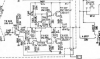
This is the section of the schematic herein the problem likely exists.
Annotation 2020-05-16 132618.png
Could be a bad transistor, could be a bad solder connection, could be.... Trying freeze spray is not a bad idea. When doing to, try to keep the spray to one component at a time (hard, as it wants to spray all over).
 
This is the section of the schematic herein the problem likely exists.
View attachment 1868436
Could be a bad transistor, could be a bad solder connection, could be.... Trying freeze spray is not a bad idea. When doing to, try to keep the spray to one component at a time (hard, as it wants to spray all over).

And why do you think in this section? (whatever section it is, remember, total newbie with next to zero ability to read a schematic! I can find things on the diagram, but schematics are still mostly greek to me). I've downloaded the documents from HiFiengine so I'll locate that area (in the amplifier section?) I bought some freeze spray today (I've seen it done on youtube. Freeze a few components and whichever melts first is faulty, correct?) I also bought some power transistors to practice changing the ones on the heatsink out.

Thanks for the input, any other direction is welcome. Working on it tomorrow.
 
This is the right side amplifier *after* the volume control. Since the volume control is not making any difference in the "fuzzy and hissy" output sound, then the problem must be introduced after the volume control.

TR602 is the input amplifier, but it's main function is to combine the input signal with the feedback signal from the amplifier output. The audio input is applied to the base, and the feedback is applied to the emitter. The output is from the collector and it represent the difference between the input and an attenuated signal from the output of the amp. The output from TR602's collector is fed to what is often called the VAS, or voltage amplifier stage. Most of the amplifiers gain is in this stage. TR605 is called a Vbe multiplier. It sets the bias between the bases of the output section to allow the idle current to be set. The output of the VAS feeds the output section which consist of a driver transistor and an output transistor.

From your previous comments, I don't expect you to understand the above, but I though it might help if you wanted to try an follow the signal through the circuit.

Don't recommend changing parts unless there is a reason to change the part. You can introduce more problems than you solve.
See what you can find in this area using the freeze spray. Use it sparingly to make it easier to isolate the possible bad area.
 
"Whichever melts first is bad" is not the way the spray works. The freeze spray will force any semiconductor or capacitor, or even a broken solder connection to fail.

You must freeze one component at a time, wait some seconds and listen for the noises to become louder or to stop. A bad transistor will react and make a difference. A good semiconductor shouldn't change the noise when frozen.

Another approach is to freeze one half of the board and see if the bad part is on that half, and then try the other half, and so dividing the areas in halves and narrow the problem. But it takes a lot of freeze spray, which is expensive down here.
 
This is the right side amplifier *after* the volume control. Since the volume control is not making any difference in the "fuzzy and hissy" output sound, then the problem must be introduced after the volume control.

TR602 is the input amplifier, but it's main function is to combine the input signal with the feedback signal from the amplifier output. The audio input is applied to the base, and the feedback is applied to the emitter. The output is from the collector and it represent the difference between the input and an attenuated signal from the output of the amp. The output from TR602's collector is fed to what is often called the VAS, or voltage amplifier stage. Most of the amplifiers gain is in this stage. TR605 is called a Vbe multiplier. It sets the bias between the bases of the output section to allow the idle current to be set. The output of the VAS feeds the output section which consist of a driver transistor and an output transistor.

From your previous comments, I don't expect you to understand the above, but I though it might help if you wanted to try an follow the signal through the circuit.

Don't recommend changing parts unless there is a reason to change the part. You can introduce more problems than you solve.
See what you can find in this area using the freeze spray. Use it sparingly to make it easier to isolate the possible bad area.


Thanks so much. Yes, I got about 20% of that, but I understand your point about following the circuit to narrow down where the problem is. I will experiment, one component at a time, with the freeze spray and see what it shows me (and what I hear!). Can I freeze components while I play music and listen? Watch and listen and when it thaws do another? Or should I give the board lots of time to thaw and dry out, and then try a different component?

Thanks for your time and expertise.
 
"Whichever melts first is bad" is not the way the spray works. The freeze spray will force any semiconductor or capacitor, or even a broken solder connection to fail.

You must freeze one component at a time, wait some seconds and listen for the noises to become louder or to stop. A bad transistor will react and make a difference. A good semiconductor shouldn't change the noise when frozen.

Another approach is to freeze one half of the board and see if the bad part is on that half, and then try the other half, and so dividing the areas in halves and narrow the problem. But it takes a lot of freeze spray, which is expensive down here.


Yes, I watched a few videos and I saw an explanation about the spray changing the sound, and then thaws and it reverts to its "bad" sound again. I will try that. As I asked YIII, can I just put music on and freeze components as it plays, one after another, listen, wait for them to thaw, freeze another, etc...while music continuously plays? Or should I freeze, listen and then shut things down, wait for thaw out and drying a bit, then do it again?

Thanks. These forums are probably the most helpful of any I've ever seen! Should have talked to you guys before I unloaded my Luxman R117!

I would love to see Buenos Aires. In Toronto a medium can of the freeze spray was $15 Cdn.
 
Yes, you use the freeze spray while listening to music. After spraying one area, allow that area to warm up a bit (at least until the frost is gone) before moving on to the next. If you start getting significant condensation, give it a minute for the condensation to evaporate. In addition to the components, you can try spraying the board itself. The cold may make worse or better any possible breaks in the runs or cracked solder connections.
 
Thanks. These forums are probably the most helpful of any I've ever seen! Should have talked to you guys before I unloaded my Luxman R117!
Got a R115 on the bench right now.
medium can of the freeze spray was $15 Cdn.
Yes, the stuff is not cheap. In a pinch, a can of 'air' (cleaner/duster) can be used if the can is held upside down. The liquid that comes out is not as cold as real freeze spray, but can be useful.
 
I never play music while using the freeze spray. Instead, I usually wear headphones and carefully listen to the noises changing with the freeze spray. In some cases is very evident (loud Pops and explosions) and in some cases you need to hear a kind of "wind" noise, changing or making small crackling noises. I prefer silence and headphones to test this kind of fails. You don't need to power off the unit, you keep freezing parts, but wait for the part to react. If you freeze different parts too soon, you don't know which part is reacting. Someties it take some seconds, perhaps a minute to reveal a noise after a freeze-heat cycle

(BTW a small can of spray, 160mL, is like $5 down here, and a large can twice that, but earning $10 here is harder than in other places. Last week a tech came home to fix my fridge, it needed a refrigerant charge, he charged me like $13 including diagnosis and the refrigerant)
 
Back
Top Bottom