• The move to the new server is done. There are some software and database maintenance updates in process. This has us passing the hat around to help out. We appreciate any donations. Seriously, even a dollar helps. The payment page may be found here - https://www.audiokarma.org/support.html

Put a capacitor in backwards and it fixes the problem???!!!

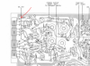
At the risk of sounding ridiculous and sorry for not asking this earlier, are we working from page 3 of the service manual, the page that says "Main amp circuit board diagram"? What is the difference between it and page 6 the "Audio amp circuit board diagram"? Page 3 is what matches my stereo inside.
Page 3 and page 6 are slightly different versions of the amp board. One contains TR608/TR609 the other doesn't. I hadn't noticed the difference until I went looking for R626. And the parts designators on the first layout do not match with the schematic. On the layout R626 is indeed 1.5K (on the schematic it is 5.6K and in a different place).
 
Page 3 and page 6 are slightly different versions of the amp board. One contains TR608/TR609 the other doesn't. I hadn't noticed the difference until I went looking for R626. And the parts designators on the first layout do not match with the schematic. On the layout R626 is indeed 1.5K (on the schematic it is 5.6K and in a different place).

I took a picture of the resistor but they aren't easy to post? I went online to verify the colours, it's 1.5k but I'll go over the traces and joints first. They look ok to my untrained eye, but I'll make sure.
 
Well, it's been a while, but in case anyone is still following. I replaced the resistor I thought might have and issue with no effect. If it helps at all, when I turn the music up it will drown out the distortion and static. It is at lower volume levels that the distortion and static is obvious, and it does not get louder with volume. Open, of course, to suggestions.
 
OK, if we are talking about distortion (not hiss) that is noticeable at low volumes but is buried at higher volumes, it's beginning to sound like cross-over distortion.
Have you got any mini-grabbers type meter leads? 8809-g.01_s500_p1._V4493a2f7_.jpg I'd like you to be able to connect your meter to a point without any chance of a probe slipping and shorting something out (and letting out the magic smoke). You earlier mentioned a ground wire you removed. Reconnect that wire if at all possible. If not possible, let me know.

Start with power off. Input select set to Aux, and volume control all the way down. Connect the black lead of your DMM to chassis ground. Connect the red lead to the emitter of TR608 as shown.Annotation 2020-06-13 120700.png Confirm that the red lead is connected only to TR608 emitter and not shorting to the collector or any other adjacent parts or circuit runs. Set the meter to the mVDC range. Turn on power and allow the reading to stabilize (may take a couple minutes). Should see nominally 10 mV.
 
Might also want to clean the speaker select switch - try to get some cleaner in there (such as Deoxit) and work it back and forth a dozen times or so. Sometimes a dirty connection can sound like what you describe.
 
Last edited:
I have cleaned all of the pots and selectors a couple of times with Nutrol. I can go over them again, just to be sure.

I don't have those clips and local stores don't seem to have them. I grounded the board again with a piece of wire (I could not reattach it and ground it and still get access.) I got some alligator clips but I cannot get into the transistors well with them. I tried it from the bottom. (If that is useful?) Going from the bottom I got no reading on the emitter of TR608. I tried the others and the only one that would give a reading was the emitter of TR508, and it slowly climbed to 4.3mV after about 2 minutes. I tried again from the top without the alligator clip, just using the DMM probes and making sure I didn't touch anything. Again, the only emitter reading I got was from TR508 and it again slowly climbed to 4.3mV after 2 minutes roughly.

Seems odd, because all of the speakers work (it has the old screw type as well as the old RCA type connectors), just the one channel has the problem.

Is that useful?
 
Alligator clips are almost always too big. You can use a 'pointed' probe if that is what you have, two-electrical-multi-voltage-meter-probes-white-background-114258425.jpg but be *very* careful not to short anything when making measurements. Sounds like the left channel (TR508) has some bias, but less than the spec. And the right channel has no bias.

I'm going to ask you to take some more voltage measurements, you can use the 'pointy' probes as long as you are careful. Before I do that, confirm for me if the picture of the board layout on page 3 of the manual is the top (component) view or the bottom (solder side) view. When you take measurements, you can connect to the component lead on the top or to the solder pad on the bottom. Either will be OK.

 
Alligator clips are almost always too big. You can use a 'pointed' probe if that is what you have, View attachment 1897257 but be *very* careful not to short anything when making measurements. Sounds like the left channel (TR508) has some bias, but less than the spec. And the right channel has no bias.

I'm going to ask you to take some more voltage measurements, you can use the 'pointy' probes as long as you are careful. Before I do that, confirm for me if the picture of the board layout on page 3 of the manual is the top (component) view or the bottom (solder side) view. When you take measurements, you can connect to the component lead on the top or to the solder pad on the bottom. Either will be OK.

OK. Page 3 seems to be the top, component view.
 
OK, let's measure the voltages at:
TR604 base
TR606 base
TR608 collector

And for comparison
TR504 base
TR506 base
TR08 collector

Please do this after the unit has warmed up for about 10 minutes, input set to Aux, volume at minimum. Post as many figures as your meter reads out. You can make the measurements from the top side or bottom side of the board, whichever is more convenient. Once again, use caution to not allow the probe to slip and short anything out.
 
Measuring from the top. Grounded the board and black probe. DMM set to 200mVDC.After warm up, on aux...

TR604 base 9.9 and very slowly dropped
TR606 base 2
TR608 collector from bottom 6.7 and very slowly dropped

And for comparison
TR504 base 8.4 dropped very very slowly
TR506 base 1.9
TR508 collector from bottom 5.3 and very very slowly dropped

Make sense? Are we trying to determine why one channel has no bias?
 
Are we trying to determine why one channel has no bias?
yes
Make sense?
no. Neither channel has rational voltages. Did you take these with the DMM set to the 200 mV range? Because these voltages are higher, you would want to use the 20 VDC range (if the meter is not auto-ranging). The collectors of TR508 and TR608 should both be around 15.00 volts, and difference in voltage between the base of TR504 and TR506 should be around 1.800 volts. Ditto for TR604/TR606. Does your meter only do two digits? Would like to see numbers like "12.45 volts" instead of "12 volts".

Let's try again to measure the voltage on the emitters of TR508 and TR608 on the 200 mV range (or 20 mV range if your meter has that). Then switch to the 20 VDC range and remeasure the points in post #49.
 
(I use to solder short leads on the solder side of a PCB to have some test points where to clip the probes, when accessing from the component side seems dangerous or I see a risk of shorting a transistor)
 
My DMM is not autoranging. In VDC I have the following settings - 1000- 200 - 20 - 2000m - 200m. My DMM is doing odd things, so I tested it on some resistors and it got the resistance correct and diode mode seems to work on some transistors I have and Ohms seems to work on some woofers I have. I replaced the battery. Testing again...

TR604 base on the 200m setting reads 00.4
TR606 base on the 200m setting reads 00.2
TR608 collector from bottom on the 200m setting reads 00.4 and on the 20VDC reads 0.00

And for comparison
TR504 base on the 200m setting reads 00.3
TR506 base on the 200m setting reads 00.2
TR508 collector from bottom on the 200m setting reads 00.2 and in 20VDC reads 0.00

In 20VDC mode I get readings of 0.00 for everything.
 
Last edited:
Luck
(I use to solder short leads on the solder side of a PCB to have some test points where to clip the probes, when accessing from the component side seems dangerous or I see a risk of shorting a transistor)

Luckily the layout so far has made it easy to access the test points, but I will heed your advice and be very careful!
 
yes
no. Neither channel has rational voltages. Did you take these with the DMM set to the 200 mV range? Because these voltages are higher, you would want to use the 20 VDC range (if the meter is not auto-ranging). The collectors of TR508 and TR608 should both be around 15.00 volts, and difference in voltage between the base of TR504 and TR506 should be around 1.800 volts. Ditto for TR604/TR606. Does your meter only do two digits? Would like to see numbers like "12.45 volts" instead of "12 volts".

Let's try again to measure the voltage on the emitters of TR508 and TR608 on the 200 mV range (or 20 mV range if your meter has that). Then switch to the 20 VDC range and remeasure the points in post #49.

The emitters of tr508 and 608 read 00.0 on 200m range. I measured from the bottom, stereo on for 10 minutes and everything grounded.
 
There must be something wrong with the voltage ranges on the DMM then. Try testing an alkaline battery (AAA, AA, C, or D sized). Should read a bit over 1.5 volts.
 
There must be something wrong with the voltage ranges on the DMM then. Try testing an alkaline battery (AAA, AA, C, or D sized). Should read a bit over 1.5 volts.

Tried several batteries, rechargeable and non on 20VDC. A and AAs tested at 1.3, 9 volts tested at 6.5-7.5.

Think I need a new 9volt in the DMM?
 
Could be. Still concerns me that on the receiver you are reading basically zero on points that should be in the mid teens.
 
I'll put in a new battery, test again, and report back tomorrow.

Do you know the voltages from the service manual, or just your knowledge of electronics?

And are we basically working back from the output transistors, testing each component, to find the reason for the lack of bias?
 
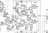
The voltages are shown on the schematic.
Annotation 2020-06-15 190205.png
15.8 volts on the base of TR504/604
15.2 volts on the emitter of TR504/604 and the base of TR507/607
14.6 volts on the emitter of TR507/607 and the collector of TR508/608 (only about 10 mV dropped across R524/624)
14.0 volts on the base of TR506/606
14.6 volts on the emitter of TR506/606
0.6 volts on the collector of TR506/606 and the base of TR508/608.

Just a little theory.... The amplifier output is at the input to C513/613. That point should be half way between the positive and negative rails. In the case of this amplifier, the positive rail is shown as +31.0 volts and the negative rail is ground. Halfway between would be +15.6 volts. Because the output stage is not quite symmetric, in practice the voltage at that output point is usually just a bit less than halfway, thus the +14.6 volts. An NPN transistor biased into its active region will have a base voltage about 0.6 volts higher than the emitter voltage. And PNP transistor will have a base voltage of about 0.6 volts less than the emitter voltage. You can use that info to calculate the voltages on almost all the transistor pins - in this case those would agree with what is posted on the schematic.

Yes, we are looking for something that isn't right, and it is important to measure these voltages accurately if we want a true picture of what is going on. But if all the voltages are wrong... well, then the amplifier wouldn't be working at all.
 
Back
Top Bottom