• The move to the new server is done. There are some software and database maintenance updates in process. This has us passing the hat around to help out. We appreciate any donations. Seriously, even a dollar helps. The payment page may be found here - https://www.audiokarma.org/support.html

Put a capacitor in backwards and it fixes the problem???!!!

The base was the pin closest to the pots? and it goes BCE?

Tr 608
Red on base black on emitter 573
Black on base red on emitter 1
Red on base black on collector 569
Black on base red on collector 1
Red on collector black on emitter 1
Black on collector red on emitter. 1


Tr 608
Red on base black on emitter 555
Black on base red on emitter 1
Red on base black on collector 554
Black on base red on collector 1
Red on collector black on emitter 1
Black on collector red on emitter. 1

I am thinking you had me do six measurements to make sure I didn't mix up the pins?(ha ha! No offense if you did!)

So, they are a little low, but is that bad?

I will need thermal compound to reattach them?(I bought some, I've done it before on subwoofer amps) I also have some TIP31B-2 replacements if needed. Are those ok?
 
Last edited:
Yes they are B-C-E. I assume "1" on your meter is the same as you see with the leads open. So that is your meters representation of "high off scale".
These transistors are all good. I figured they would be but we are getting mixed results just measuring voltages. Leave them out for now, but when you reinstall, yes, fresh thermal paste is a good idea - just be sure it is a non-conductive thermal paste and not something that contains silver or other metallic filler. .

I had you take 6 measurements because that is what is needed. To test a diode, you need to measure it in both directions. So there are 2 measurements per diode. For basic testing purposes, a transistor looks like 2 diodes (B-E and B-C), so total of 4 measurements. Then you also need to check for a C-E short. Probably really only need to do this in one direction, but doing it in both is more complete. So 4 + 2 = 6.
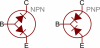
transistors-as-diodes.png

This may come down to an adjustment, but it seems like the bias is far enough off that just a drift in the adjustment would not be the whole story. (unless someone has messed with VR606). So let's also remove and test the driver transistors. These would be TR604 and TR606. With the flat up and the leads down, the basing on these is E-C-B. You should see measurement very similar to those of the outputs.
Note: The two output transistors are the same part number and can be put in either spot. That is not true for the drivers one is NPN and the other is PNP. Keep track of which one came from where.
 
By down, you mean pins facing me? Flat side up, pins facing me,(the schematic makes it clear too)

Tr 606
Red on base black on emitter 1
Black on base red on emitter 770
Red on base black on collector 1
Black on base red on collector 755
Red on collector black on emitter 1
Black on collector red on emitter. 1


Tr 604
Red on base black on emitter 772
Black on base red on emitter 1
Red on base black on collector 764
Black on base red on collector 1
Red on collector black on emitter 1
Black on collector red on emitter. 1

They're good?
 
Yes, those are all good too. Leave them out for now, but don't lose track of which one came from where. Only one left to test.Remove and test TR605.

Also, with TR605 removed, use the meter probes to look at D601. Test it in both directions just as you do a transistor junction. Schematically, this is shown as two diodes in series, so you my get "1" in the reverse biased direction and around "1.30" in the forward biased direction.

While we got things open, use the ohmmeter function to check the resistance of R621 and R622. These should be 330 ohms (orange-orange-brown), so use the 2K range on your meter. Normally you need to remove parts from a circuit to get accurate measurements, but since the transistors are out, you can measure them in-circuit.

Now put the meter on the 2 ohm range. Short the leads and note the reading. That is the resistance of your meter leads. Measure R624 and R625. Subtract your meter lead resistance from these measurements to get the actual values of these emitter resistors. Should be near 0.47 ohms.
 
While I have you measuring things, measure the resistance across the 10K variable resistor VR606. Use the 20K ohm range on your meter.
Annotation 2020-06-18 162835.png
 
While I have you measuring things, measure the resistance across the 10K variable resistor VR606. Use the 20K ohm range on your meter.
View attachment 1901628


Tr 605
Red on base black on emitter 777
Black on base red on emitter 1
Red on base black on collector 759
Black on base red on collector 1
Red on collector black on emitter 1
Black on collector red on emitter. 1

D601 was 1522 and 1.(test in diode mode?) I checked from above and below.

R621-333 ohms
R622-322 ohms

My DMM has 200ohm. Shorted gave 0.8.
R525 was 1.2 (so 0.4?)
R524 was 1.2 also. So they're solid?

VR606-4.50 at 20k setting.
 
Everything is looking good. Reinstall TR604 ('C828), TR605 ('C828), and TR605 ('A564). Leave the output transistors out for now.
Note the position of VR606, and use a bit of cleaner on it. Deoxit or a generic contact cleaner is OK. Work it back and forth a bit then return it to it's original position.

Power up the receiver and measure the voltage *across* R621 and R622 (the meter's 2 volt range would be appropriate). The two voltages should be very close to the same.

Adjust VR606 and observe the change in voltage across R622. Adjust VR606 for 0.55 volts across R622. Check to see if the voltage across R621 is also very close to 0.55 volts.

Post the original voltages you see across R621 and R622, and the voltage you see across R621 after adjusting for 0.55 volts across R622.
 
Everything is looking good. Reinstall TR604 ('C828), TR605 ('C828), and TR605 ('A564). Leave the output transistors out for now.

Done
Note the position of VR606, and use a bit of cleaner on it. Deoxit or a generic contact cleaner is OK. Work it back and forth a bit then return it to it's original position.

Done

Power up the receiver and measure the voltage *across* R621 and R622 (the meter's 2 volt range would be appropriate). The two voltages should be very close to the same.

My DMM has 2000m(is that 2000 millivolts, aka 2 volts?) I get nothing for r621 at that setting, it says 1. I had to measure from the bottom(no room above.).
R622 measured 248 at that setting.
I moved it to the 20volt setting. R621 was 13.01 and R622 was 0.24. I adjusted VR606 clockwise and got R622 to 0.52 (any more rotation and it went down) and R621 was 12.92.

Adjust VR606 and observe the change in voltage across R622. Adjust VR606 for 0.55 volts across R622. Check to see if the voltage across R621 is also very close to 0.55 volts.

Post the original voltages you see across R621 and R622, and the voltage you see across R621 after adjusting for 0.55 volts across R622.
 
I moved it to the 20volt setting. R621 was 13.01 and R622 was 0.24.
Weird. The current flowing through TR604 and R621 should also flow through TR606 and R622. So the voltage across R621 and R622 should be the same.
Try removing C609, set VR606 back to where it was originally, and then look at the voltages across R621 and R622. Are they closer to the same?
 
Weird. The current flowing through TR604 and R621 should also flow through TR606 and R622. So the voltage across R621 and R622 should be the same.
Try removing C609, set VR606 back to where it was originally, and then look at the voltages across R621 and R622. Are they closer to the same?

C609 removed. (Not 610?) Vr606 back to original, voltages were identical.
 
I'm really scratching my head on this one. What model of DMM do you have? Does it by any chance have the ability to measure a transistors hFE? Or do you maybe have a component tester than can do that?

Measure the voltage across D601.
Now measure the voltage across D501.
 
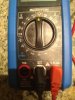
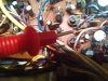
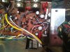
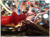
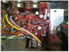
I added those pictures in case something was wonky. That is my DMM. But my stereo doesn't seem to match the diagram exactly. I am pointing between VR506-606 and I have the yellow...is that diode D601? It doesn't look like one but I'm such a rookie so I measured those. The wires beside it that lead to the output transistors 507 and 607, those aren't the diodes there are they? . Does that seem right? Measuring the yellow diode 601 at 200VDC gets 1.4. measuring 501 gets 0.6.

Should I be measuring those wires where they meet the board or up on the transistors? Has someone altered the receiver?
 
Last edited:
The yellow disks are disk capacitors, C514 & C614. You guessed right that the diodes are at the heat sink on the end of those wires. The leads on the diodes can be delicate, so measure the voltage across C514 & C614. Those will be the same as the voltages across D501 & D601. Use the 2 volt range.
Annotation 2020-06-19 211523.png Annotation 2020-06-19 212038.png
In similar circuits, those diodes *are* normally thermally coupled to the heat sink, but the layout in your manual shows them on the circuit board. Wouldn't be the first time the manual isn't quite right :)

Those diodes are listed in the parts list as "1S188" diodes. Full data sheets on this seem to be hard to find. What I have found indicate it is a germanium diode, with a max forward voltage drop of 1.0 volts. So 1.4 is too high and 0.6 is too low (another :) )

After measuring the voltage across D601/C614, also measure the voltage between the base of TR604 and TR606. We've got to be missing something obvious.
 
At 2V c 614 was 898.
C514 was 1213. I measured from above which made it hard to make good contact, but those were the most stable numbers I got. Close enough to spec?

So, I put one probe on 604 base and one on 606 base? I got 1574 at 2V setting.
 
C614 was 898.
C514 was 1213.
That can certainly be the problem.

I put one probe on 604 base and one on 606 base? I got 1574 at 2V setting
Yeah that is too low Confirms that D601 is likely the problem. Think we are going to need to find a 1S188 or a substitute. I'm going to be busy this morning, but I look around a bit and get back to you later this afternoon.
 
That can certainly be the problem.

Yeah that is too low Confirms that D601 is likely the problem. Think we are going to need to find a 1S188 or a substitute. I'm going to be busy this morning, but I look around a bit and get back to you later this afternoon.

Certainly no rush. Thanks again for your help. I will play with the sanyo turntable that won't auto return!
 
Put on the brakes, I was looking at the wrong part in the parts list. That diode that seems to be bad is a "KB-269".
 
Back
Top Bottom