• The move to the new server is done. There are some software and database maintenance updates in process. This has us passing the hat around to help out. We appreciate any donations. Seriously, even a dollar helps. The payment page may be found here - https://www.audiokarma.org/support.html

Put a capacitor in backwards and it fixes the problem???!!!

Put on the brakes, I was looking at the wrong part in the parts list. That diode that seems to be bad is a "KB-269".

Not made anymore... found this on Audiokarma..."appears to be a..Si, ¼W, 2V zener. According to some sources, it can be replaced by BZ102/2V1, BZV86/2V0, BZX75/C2V1, ZTE 2, and others." Others have run into this problem if finding a replacement.

Or this...

Replacement diode stack. I used three 1N4148, cause I had in hand in that time. Did the trick for me.
 
Last edited:
BZX75/C2V1
BZX75/C1V4 looks to be the best match, but as you say, that one seems to be unobtainium too.

General consensus seems to be to replace it with a series connected pair of 1N4148's. But I did a sim on it, and just dropping in the 1N4148's leaves things a bit short on bias. That is assuming the 1N4148 model in the sim program is accurate. Adding a series resistor with the 1N4148's can get the voltage up to where it needs to be but the adjustment becomes very touchy (they usually are but the sim seems to indicate this would be more touchy than usual). That touchiness can be reduced a bit by adding a resistor in parallel with the adjustment pot.

Anyway, I offer the following for your consideration....
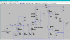
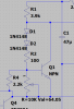
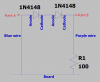
Disconnect the KB-269 from its terminal strip at the heat sink. In its place, add a series network of qty 2 1N4148 diodes and a 100 ohm resistor. Observe polarity as shown in the schematic (or by reference to original part). The diodes should be positioned so that they make thermal contact with the heat sink in the same manner as the KB-269 did, but be careful not to allow the leads to short to the heat sink or to each other. The resistor can be positioned anywhere. Then add a 2.2K resistor from the high side of the pot to the low side of the pot. We will want to take some measurements before reinstalling the output transistors, as the real world is not always the same as a simulation. You would have the assortment below in case we needed to tweak some values.

The 1N4148's are available at your store, https://secure.sayal.com/STORE2/View_SHOP.php?SKU=247726 would be my choice.
For the resistors, they have an assortment that contains the required values. https://secure.sayal.com/STORE2/View_SHOP.php?SKU=223948

In the pix, ignore the component identifiers - the sim program assigns them and I didn't go through and edit them. The pot is VR606 and Q1 is actually TR605.
Annotation 2020-06-20 225331.png Annotation 2020-06-20 225437.png
 
Wow, this is a lot of effort for a 50 year old $5 receiver! I feel bad that you have put in so much effort! But I appreciate it all, and I love not seeing stuff go to the dump.

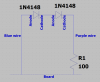
I will pick up the parts tomorrow or Tuesday. I will probably semi- assemble it and take a picture to verify that I am doing it correctly. So the diodes and resistor are going along the blue and purple wires, where kb269s were? Crowded, but I'll figure it out.At the same time I'll show you a picture of how I'll solder the resistor in parallel with VR606.

Thanks again, I'll hit sayal tomorrow.
 
Last edited:
Sounds good. I'm glad you don't consider it a high value item, as I *hate* making changes to circuitry. After all, a highly paid engineer did the original design, and supposedly he/she knew how to do it. But when parts become unavailable sometimes you have to make changes.

When putting the resistor in series with the diodes, do it in such a way as it will be easy to change it. You may actually want to put just the diodes up by the heat sink and put the added series resistor in line with one of the wires at the circuit board - just lift one of the wires and add the resistor in between the wire and the board. Remember that when things are in series, it does not matter what order they are in We may have to juggle some resistor values to get the adjustment range where we want it.

Are we having fun? Yes!
 
Ok, got the components. Resisters are non polar, correct? So that's easy. Diodes have polarity, right? So, to be clear, how should the diodes be attached in relation to the blue and purple wires?(I'm not replacing both channels right?)

And in the VR606, which pins do I attach the resistor to?(again, I'd hate to make a mistake now)
 
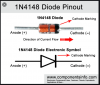
Resistors are non-polar. You are working only one channel. A diode has an anode and a cathode.
Annotation 2020-06-23 172343.png
You want to connect two diodes in series with the cathode of the first soldered to the anode of the second. Keep the distance between the first and second to a reasonable length, but you do not want to over stress the leads and physically break the diodes. Carefully desolder and remove D601 and put this diode pair in it's place. Then on the other end of the purple wire, lift it from the board, and install the 100 ohm resistor between the board and the wire.
Annotation 2020-06-23 172243.png

Let's leave the shunt resistor across VR606 off for now, and take some measurements. Turn VR606 fully CCW.
Measure the voltage from point A to chassis ground
Measure the voltage from point B to chassis ground
Measure the voltage between point A and the emitter of TR605.
Annotation 2020-06-23 172243.png
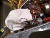
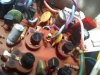
Then a picture or two of your work may be helpful.
 
One other thing. After making the above measurements, set VR606 to about 75% of its CW rotation and remeasure the voltage between point A and the emitter of TR605.
 
Resistors are non-polar. You are working only one channel. A diode has an anode and a cathode.
View attachment 1906452
You want to connect two diodes in series with the cathode of the first soldered to the anode of the second. Keep the distance between the first and second to a reasonable length, but you do not want to over stress the leads and physically break the diodes. Carefully desolder and remove D601 and put this diode pair in it's place. Then on the other end of the purple wire, lift it from the board, and install the 100 ohm resistor between the board and the wire.
View attachment 1906451

Let's leave the shunt resistor across VR606 off for now, and take some measurements. Turn VR606 fully CCW. Done
Measure the voltage from point A to chassis ground says 1
Measure the voltage from point B to chassis ground says 1
Measure the voltage between point A and the emitter of TR605. Says 1691 at 2v.
View attachment 1906479
Then a picture or two of your work may be helpful.
 
Last edited:
One other thing. After making the above measurements, set VR606 to about 75% of its CW rotation and remeasure the voltage between point A and the emitter of TR605.

At 3/4 rotation (which was roughly its original setting), at 2v, it jumps around a lot, around 1400
 
Last edited:
Changes look OK for now (after reversing those backwards diodes :).

If your meter reads "1", that is an over range and you need to change the meter setting. If it is on the 2V range and you get a "1", then you need to change the meter to the 20 volt range. You want the meter on the most sensitive range you can while not getting an over range reading ("1"). Here, you are going to want to use the 20 volt range.

Measure the voltage from point A to chassis ground
With VR606 fully CCW,
Measure the voltage from point B to chassis ground
Measure the voltage between point A and the emitter of TR605.
Set VR606 to about 75% of its CW rotation and remeasure the voltage between point A and the emitter of TR605
 
Position A to ground 13.92v. b to ground 12.87. A to emitter of transistor at 3/4 rotation 1.74. All the way CCW 1.67.
 
Good believable numbers, but too low. I though that might be the case - please change the 100 ohm resistor to 470 ohms (yellow-violet-brown) and repeat the measurements. I'm looking for the point 'A' to TR604 emitter voltage to be less than 1.9 volts with the pot fully CCW, and around 2 with the pot about 75%.
 
Good believable numbers, but too low. I though that might be the case - please change the 100 ohm resistor to 470 ohms (yellow-violet-brown) and repeat the measurements. I'm looking for the point 'A' to TR604 emitter voltage to be less than 1.9 volts with the pot fully CCW, and around 2 with the pot about 75%.

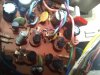
First thing Thursday morning. Shouldn't the higher ohms lower the measurement? I seem to be missing some fundamental understanding.
 
There is a current flowing from the anode of the first diode, through the second diode and then thru the resistor to the base of the transistor. Some of that base current is bypassed by the adjustable resistor VR606.

So in this series string we have two diodes (for a drop of 0.6 each or 1.2 volts), the drop across the added resistor, and the base emitter drop of the transistor (0.6 volts). Without the added resistor that adds up to about 1.8 volts. We need a bit more than that to turn on the following stages. We get that extra voltage via the drop across that added resistor - the higher that resistor value, the more voltage will drop across it; hence the higher the bias voltage (collector (or 'point A') to emitter of TR605).

Clear as mud?
 
Back
Top Bottom