• The move to the new server is done. There are some software and database maintenance updates in process. This has us passing the hat around to help out. We appreciate any donations. Seriously, even a dollar helps. The payment page may be found here - https://www.audiokarma.org/support.html

Put a capacitor in backwards and it fixes the problem???!!!

There is a current flowing from the anode of the first diode, through the second diode and then thru the resistor to the base of the transistor. Some of that base current is bypassed by the adjustable resistor VR606.

So in this series string we have two diodes (for a drop of 0.6 each or 1.2 volts), the drop across the added resistor, and the base emitter drop of the transistor (0.6 volts). Without the added resistor that adds up to about 1.8 volts. We need a bit more than that to turn on the following stages. We get that extra voltage via the drop across that added resistor - the higher that resistor value, the more voltage will drop across it; hence the higher the bias voltage (collector (or 'point A') to emitter of TR605).

Clear as mud?

I totally gapped that lower ohms means less resistance...duh! Remembered as soon as I posted! And I'm starting to get voltage drop, bias, and how it will turn on circuits. Going to switch the resistor now.
 
470ohm resistor. Had to move dMM up to 200v. A to ground 26.5. B to ground 25.6. A to emitter of tr605 14.8, and 3/4 rotation 14.8.

220ohm resistor. 200v setting. A to ground 26.7. B to ground 25.8. A to emitter all the way CCW 15, 3/4 rotation 15.

When I desoldered the purple wire to put in the resistor I lost some of the trace. I added extra solder to make sure the resistor and VR606 we're making contact, but could that be why VR606 isn't adjusting the voltage?
 
When I desoldered the purple wire to put in the resistor I lost some of the trace. I added extra solder to make sure the resistor and VR606 we're making contact,
That repair looks good.

470ohm resistor. Had to move dMM up to 200v. A to ground 26.5. B to ground 25.6. A to emitter of tr605 14.8, and 3/4 rotation 14.8.
220ohm resistor. 200v setting. A to ground 26.7. B to ground 25.8. A to emitter all the way CCW 15, 3/4 rotation 15.
These I don't understand. Did you possible use the 4.7K and 2.2K resistors instead of the 470 ohm and 220 ohm resistors? 4.7K would be yellow-violet-red, while 470 ohm would be yellow-voilet-brown. Even that shouldn't allow the voltage at point A to go that high. Check TR605 for broken leads or a bad solder connection. And check the runs in the area for any breaks. It's possible we lost TR605, but I don't see any reason we should have.

Try the 100 ohm resistor again and see it you can get back to the numbers you had in post #118. If not, then I will need the voltage readings at:
Point 'A' to ground -
Junction of the two new diodes to ground -
Point 'B' to ground -
Base of TR605 to ground -
Emitter of TR605 to ground -

Also, the little plastic cap came off the VR knob. I promise I did not crank it! It was brittle!
Is it still adjustable?
 
Tr606 still adjustable. 100ohm resistor got the same crappy numbers. I double checked the resistors and put them on my DMM and they tested correctly...459 ohms. I touched up my solder joints, they seem good.

A to ground 27.2v.
B to ground 26.3v.
Joint between A and B to ground 25.8v.
Base of tr605 to ground 11.8v.
Emitter of tr605 to ground 11.9v.
These were both with 100 ohm resistor and VR606 full CCW. At 3/4 rotation exact same numbers for tr605. If I turn VR606 fully CW I get 11.9v and 11.9v.
 
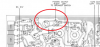
Took another look at the picture you posted in #125. It looks like there is a break in one run and a solder bridge between two runs. (Plus a scratch?) See attached. Note your picture is the board bottom, and the second picture posted is the layout from a top view.
IMG_20200625_091633684.jpg Annotation 2020-06-25 215418.png
Remove the existing solder bridge and fix the break in the run along the board edge. Then let's see another picture of the area.
 
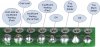
Just a comment on your soldering. Don't know what iron you are using or what temperature it is set at, but it looks like the connections have not fully 'flowed'. You might want to keep your iron on the point you are soldering for a second or so longer so the solder fully flows. Some of yours look like the second from the left in this picture.
tools_Header_Joints.jpg
 
It looked so natural and deliberate I would not have thought it was a break! Shall I use a piece of solder to bridge it?
Where you indicated a bridge there is no actual connection, but I will confirm.
Is there a way to repair the scratch?

My iron is set at 480 degrees, which I know is high. I will try at a lower setting and try for better flow.
I'll send some pics.
 
The break is large enough that you might want to bridge it with a wire and not just a solder bridge. Use a piece of resistor lead cut-off.
So the bridge was an artifact of the photo angle. Good.
Scratch is not a problem if that is what it is. I was concerned it might have been a solder whisker.
480°F? or 480°C. Assuming you are using 60/40 or 63/37 solder, setting the iron to 700°F (370°C) is common. If you are using lead free solder, then 750°F (400°C) is OK. Any hotter than that will only shorten the life of your soldering tip. Too hot an iron can also oxidize the flux before it has a chance to do its job.
 
My solder is conductaloy superset, silver bearing with no corrode flux. I lowered the iron to 370C. I see it flowing better.

IMG_20200627_123450982.jpg IMG_20200627_123429729.jpg

A to ground 26.2
B to ground 25.3
A to emitter at 3/4 rotation 14.8
 
Last edited:
Might want to consider a more conventional solder. Next time you are there, https://secure.sayal.com/STORE2/View_SHOP.php?SKU=221737 looks good.

But is seems like something changed that we are not seeing. You're getting better at this, changing meter ranges as require. You want to use the lowest range possible to get the most significant figures, but remember that if the meter reads "1", that means the input is higher than can be measured on that range. If the voltage is, for example, 2.3 volts, then you will get a good measurement on the 20 volt range, but the 2 volt range will read "1" or overrange. If you use the 200 volt range, you loose a digit of resolution.

So let's see if we can figure out what is going on here. Leave whatever resistor you have installed in series with the diodes (100 ohms still there?), Set VR606 fully CCW. I need you to measure the voltage on the following:

TR604
Emitter -
Collector -
Base -

TR605
Emitter -
Collector -
Base -

TR606
Emitter -
Base -
Collector -
 
Some of those traces look fried. I refer to the centre area of the image to the left of one repair. Also a couple spots below the black wire the component leads look to have poor connections.
 
Some of those traces look fried. I refer to the centre area of the image to the left of one repair. Also a couple spots below the black wire the component leads look to have poor connections.

Yup, total rookie here. YIII has been unbelievably patient. Learning to let the solder flow better.
 
We all deal with the learning curve my friend. All I can recommend is that you use some good old-school 60/40 lead solder. They silver based stuff and the newer lead free are not great for building your chops. Experienced people have trouble with it. It's good to have different tips, adjustable temperature and a few different solder sizes. You'll learn over time how to use these options to your advantage.

Ylli has helped me in the past, he has an ability to teach without making the student feel stupid. I'm really enjoying this thread.
 
Might want to consider a more conventional solder. Next time you are there, https://secure.sayal.com/STORE2/View_SHOP.php?SKU=221737 looks good.

But is seems like something changed that we are not seeing. You're getting better at this, changing meter ranges as require. You want to use the lowest range possible to get the most significant figures, but remember that if the meter reads "1", that means the input is higher than can be measured on that range. If the voltage is, for example, 2.3 volts, then you will get a good measurement on the 20 volt range, but the 2 volt range will read "1" or overrange. If you use the 200 volt range, you loose a digit of resolution.

So let's see if we can figure out what is going on here. Leave whatever resistor you have installed in series with the diodes (100 ohms still there?), Set VR606 fully CCW. I need you to measure the voltage on the following:

VR606 fully CCW. Stereo on for 10 minutes, volume at 0. Black probe grounded,

TR604
Emitter - 25.4
Collector -27.4
Base - 26.0

TR605
Emitter -11.58
Collector - 26.2(from top and bottom)
Base -11.43

TR606
Emitter -12.33g
Base -11.53
Collector -- 12.18 (this is the collector not the base)

I had to switch range, some went off range.
 
We all deal with the learning curve my friend. All I can recommend is that you use some good old-school 60/40 lead solder. They silver based stuff and the newer lead free are not great for building your chops. Experienced people have trouble with it. It's good to have different tips, adjustable temperature and a few different solder sizes. You'll learn over time how to use these options to your advantage.

Ylli has helped me in the past, he has an ability to teach without making the student feel stupid. I'm really enjoying this thread.

Will do!
 
I think you have an issue with one of the new 1N4148 diodes. You have 26.0 volts on 'point A' and 11.43 volts on the base of TR605. One of the diodes has gone open or there is a break in the series string connection of the two diodes and the added resistor. If all the connections look good, unsolder the connection between the two diodes and check each of them with your meter in the diode mode. Should get '1' in one direction and about 0.600 in the other direction for each diode. If you find a bad one, replace it - that's why you got extras :).

One other thing I see - is that a break in the circuit run or just an artifact of the picture?
Annotation 2020-06-27 193549.png
 
Last edited:
I'll get it done Sunday and report.
That is the resistor we added to the purple wire. It's not a break, but I'll flow some solder there to freshen it up.
 
Back
Top Bottom