
• The move to the new server is done. There are some software and database maintenance updates in process. This has us passing the hat around to help out. We appreciate any donations. Seriously, even a dollar helps. The payment page may be found here - https://www.audiokarma.org/support.html

Put a capacitor in backwards and it fixes the problem???!!!

Somewhere in that loop between the board, the diode pair, the resistor, and back to the board seems to be open. It could be one of the diodes failed open, so you will want to test those. Should be about 1.2 volts between the collector and base of TR605, constrained by the diodes, and you have about 14.7 volts.
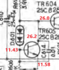
Annotation 2020-06-27 212648.png
 
Position A to ground 13.92v. b to ground 12.87. A to emitter of transistor at 3/4 rotation 1.74. All the way CCW 1.67.

Wire had broken at position B of diodes, can't believe I didn't see it. New measurements,
A to ground 13.72.
B to ground 12.73
A to emitter of tr605 full CCW 12.05
At 3/4 rotation 12.03
 
Somewhere in that loop between the board, the diode pair, the resistor, and back to the board seems to be open. It could be one of the diodes failed open, so you will want to test those. Should be about 1.2 volts between the collector and base of TR605, constrained by the diodes, and you have about 14.7 volts.
View attachment 1910467

Collector 13.77
Base 12.69.

100 ohm resistor at 3/4 rotation.
 
A to emitter of tr605 full CCW 12.05
At 3/4 rotation 12.03
These don't make sense.
What do you see on the emitter of TR605 to ground?

Base is at 12.69, so the emitter should be 0.6 volts lower than that (typical B-E drop) or 12.09 volts.
That would make C-E = 13.77 - 12.09 = 1.68 volts. Not 12.

Please confirm voltage to ground:
TR605 Emitter
TR605 Collector
TR605 Base.

Sorry I have to keep asking you to remeasure these, but things seem to keep changing, and/or there are inconsistencies to resolve.
 
Last edited:
These don't make sense.
What do you see on the emitter of TR605 to ground?

Base is at 12.69, so the emitter should be 0.6 volts lower than that (typical B-E drop) or 12.09 volts.
That would make C-E = 13.77 - 12.09 = 1.68 volts. Not 12.

Please confirm voltage to ground:
TR605 Emitter 12.08
TR605 Collector 13.83
TR605 Base. 12.75

Sorry I have to keep asking you to remeasure these, but things seem to keep changing, and/or there are inconsistencies to resolve.[/QUOT

No problem, I just hope I'm not the problem! I have not checked the diodes like you asked because I assumed the broken purple wire was the problem. Still have the 100ohm resistor in and VR606 was at 3/4 rotation.

Those readings show tr605 is ok? Or do we need exactly 0.6 voltage drop?
 
TR605 Emitter 12.08
TR605 Collector 13.83
TR605 Base. 12.75
13.83 - 12.08 = 1.75 volts. Good.
Is this with the 100 ohms and the pot fully CCW? If so, set the pot at about 75% and again measure
TR605 Emitter
TR605 Collector
 
Missed the last part of your reply above. No, you're not the problem, you are doing just fine, but you are replying within the quotes and your reply does not stand out from my post.. I do have to reconfirm things when I see inconsistencies. OK, so that was with the 100 ohm resistor and the pot at 75%. Let's leave the pot where it is (so we don't wear it out :), and install the 470 ohm resistor.
Then measure:
TR605 Emitter
TR605 Collector
 
13.83 - 12.08 = 1.75 volts. Good.
Is this with the 100 ohms and the pot fully CCW? If so, set the pot at about 75% and again measure
TR605 Emitter
TR605 Collector

100 ohm yes.
No, that was at 3/4. I've left the stereo on for a while since my last measurements to get warm. Now at 3/4, full CCW, full CW.
Emitter 12.16, 12.19, 12.23
Collector 13.89, 13.84, 13.51

Those numbers seem funky? I don't think I'm forcing it, the stops seem obvious. But it does not seem to stop at the 12 o'clock position.
 
No, that was at 3/4. I've left the stereo on for a while since my last measurements to get warm. Now at 3/4, full CCW, full CW.
Emitter 12.16, 12.19, 12.23
Collector 13.89, 13.84, 13.51
So at fully CCW, we have 13.84 - 12.19 = 1.65 volts
At 75% we have 13.89 - 12.16 = 1.73 volts
Fully CW we have 13.51 - 12.23 = 1.28. ******

*****There is a reason I haven't had you take measurements at fully CW. I mentioned earlier that this was a somewhat unconventional Vbe multiplier configuration. As you turn the adjustment CW, you are shunting current from the base of TR605, effectively reducing it's gain (hFE). As you turn the pot CW, the TR605 collector - emitter voltage will increase. But as you approach fully CW, you are also shorting out the normal base to emitter voltage of the transistor and the collector-emitter voltage will go down again instead of the steady increase. That is why I have been keeping you in the fully CCW to about 75% range. No damage going further CW, but not useful either.
 
Those numbers seem funky? I don't think I'm forcing it, the stops seem obvious. But it does not seem to stop at the 12 o'clock position.
numbers were good. We are back on the right path. The pot will have a stop at fully CCW and fully CW, there will be no center detent.
 
470ohm resistor, 3/4 rotation.

Emitter to ground 12.04
Collector to ground 13.40
Base to ground 12.70

Only on 3-4 minutes, maybe not fully warmed up.
 
Hey, just bought a Vector Research VR3000 for fun. Can't find exact numbers on line. Can I use the DMM to measure output?

Thought I'd ask.
 
470ohm resistor, 3/4 rotation.

Emitter to ground 12.04
Collector to ground 13.40
Base to ground 12.70

Only on 3-4 minutes, maybe not fully warmed up.
13.40 - 12.04 = 1.36 volts. Hmm, the voltage should have gone up significantly. What do you get for the collector and emitter with the pot fully CCW?
 
Don't find a service manual for the VR-3000 online, so can't really comment on it too much. You can use the DMM to measure output offset voltage by simply connecting the meter across the speaker output terminals . If the output is capacitor coupled, then you need to also have the speakers connected or you will get an invalid reading. (without a manual, I can't say for sure if the output is capacitively coupled or not, it likely is.)
 
13.40 - 12.04 = 1.36 volts. Hmm, the voltage should have gone up significantly. What do you get for the collector and emitter with the pot fully CCW?

I left the receiver on all morning and get, at full CCW,
Emitter 11.94
Collector 13.62
 
Don't find a service manual for the VR-3000 online, so can't really comment on it too much. You can use the DMM to measure output offset voltage by simply connecting the meter across the speaker output terminals . If the output is capacitor coupled, then you need to also have the speakers connected or you will get an invalid reading. (without a manual, I can't say for sure if the output is capacitively coupled or not, it likely is.)

Thought it would be tough. Yes, not much online. Pots needed cleaning, and a light replaced, but sounds very good. I think at least 25 watts a channel, maybe more.
 
I left the receiver on all morning and get, at full CCW,
Emitter 11.94
Collector 13.62
13.62 - 11.94 = 1.68 volts.

OK, let's go with that. I've got an errand to run, so will have to get back to this in the afternoon.
 
Back
Top Bottom