• Please note that Audiokarma will be offline briefly for updates early on Monday morning, September 28th.

Put a capacitor in backwards and it fixes the problem???!!!

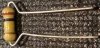
OK, dig out a 2.2K resistor from your stock. That would be red-red-red, but double check with your ohmmeter. You will need to bend the leads like in one of these pictures depending on the lead spacing you need. Cut the leads to about 1/2" long.
image1.jpg images.jpg

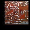
The resistor will be installed in parallel with VR606. Picture attached. Be sure the leads of the resistor do not short against any other conductors on the board.
Annotation 2020-06-29 131920.png
Once again, with the pot fully CCW, I need the voltages at
TR605 Collector -
TR605 Emitter -
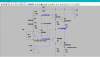
 
Emitter 12.00
Collector 13.98
2.2k resistor and full CCW.
Soooo close, might be a bit high.

Just so that we don't blow the output transistors when we test, I'd like you to add a 470 ohm resistor in series with that 2.2K resistor. Trim the leads of a 470 ohm to 1/2" or a bit less. Lift one end of the 2.2K resistor and solder the 470 ohm resistor in between the now open lead of he 2.2K resistor and the point from where it was soldered. Be sure the junction of the two resistors does not short to anything. You now have a 2.67K resistor connected where you originally had the 2.2K.

I know I am working you hard, so just a note of explanation of what we are trying to do here. We are trying to select resistor values such that we can adjust for 10 mV across the output emitter resistor R625 with the pot in the first 50% of it's rotation. The 'touchiness' of the adjustment get much worse as the pot is adjusted further CW. Right now with the 2.2K resistor across VR606, we have 1.98 volts between the collector and emitter of TR605 - Depending a great deal on the variations in the following transistor Vbe's, that may make the output bias current higher than that 10 mV with the pot fully CCW. I have the relevant portion of the circuit set up in a simulator, but I do not have accurate models for the particular transistors used. I have to use transistors that I have models for and they will differ slightly from what is actually installed in the amp. That's why we have to do the tweaking on the actual circuit.

I'm not having much luck explaining that clearly, but it means we need to bump that 2.2K resistor to 2.7K to be sure we have some adjustment range. You don't have 2.7K in your 'kit', so we can just use 2.2K in series with 470 ohms to get 2.67K which is close enough.

So add the 470 and again post the collector and emitter voltages of TR605 with the adjustment fully CCW..
 
Don't worry about me! I can not believe someone with your expertise is offering up so much of your time. I have learned a ton and realize how much I need to learn.

I understand the basic concept of what we/you are trying to do. If the voltages are not correct the next stages of the circuit essentially won't work? I am doing some research on the side about reading schematics so I can tell what voltages are required where.

I'll put in the resistor in the morning and let you know. (Starting to look like a bit of a dog's breakfast in there!)
 
13.36 - 11.94 = 1.42, would not have expected that big a change. Sim says the C-E voltage should have dropped from 1.98 volts to about 1.93 volts. Please check your work in this area:
Annotation 2020-06-30 111324.png
Let's proceed and bring the rest of the circuit back into play.

Reinstall the output transistors. Don't forget the flat insulators, any other insulating installation hardware, and a bit of new non-conductive thermal compound if you have it.
Leave VR606 fully CCW.

You will want to set up to measure the voltage across resistor R625. This will be equivalent to TR608 emitter to ground. I've marked what I believe will be the most accessible points to connect your meter. Set the meter on the 200 mV DC range.
Annotation 2020-06-30 102016.png

Since you don't have ez-hook meter probes, the next will take three hands. If you have someone nearby to help that would be great. Plug in the receiver, but have it turned off. Connect the meter to the points indicated** and have someone turn the receiver on. Watch the meter! If it reads above 10 mV, quickly note the reading and turn the receiver off. If it reads below 10 mV, allow it to warm up a bit - while watching the meter - and see where it settles out. If it drifts above 10 mV, turn it off and report.

** with the outputs reinstalled, we are at an increased risk that a slipped probe could damage a part. So use care.
 
Back together. Measured from the bottom, is that ok? If not, I am dropping by Sayal tomorrow and I'll grab the good probes. Let me know if there is anything else I should grab. (Regular solder.)

The reading climbed very quickly to 15.1, I got scared and shut it down. I did it a few times, each time the same. It looked like it would climb indefinitely.

I got my son to turn it on while I measured from above. Same result.
 
Last edited:
Close. Remover the 2.2K + 470 series combination and install a 3.3K resistor. (orange-orange-red). Repeat the above test.

In addition, if the bias is below 10 mV and you can leave it on, post the voltage at the collector of TR608.

Looking back, now that you have more experience, you may want to improve the lead dress on the 1N4148 diodes. Shorten up the leads a bit and position the diodes close to, but not shorting to, the heat sink. Ideally, you want the diode temperature to track the output transistor temperature. Let me know if you have any question on that.
 
Close. Remover the 2.2K + 470 series combination and install a 3.3K resistor. (orange-orange-red). Repeat the above test.

In addition, if the bias is below 10 mV and you can leave it on, post the voltage at the collector of TR608.

Looking back, now that you have more experience, you may want to improve the lead dress on the 1N4148 diodes. Shorten up the leads a bit and position the diodes close to, but not shorting to, the heat sink. Ideally, you want the diode temperature to track the output transistor temperature. Let me know if you have any question on that.

Voltage kept climbing slowly. It took at least a minute to get to 10 and was still rising.

11.78 at collector.
 
Last edited:
New adjustment pot....... Monitor the voltage on the collector of TR608 and adjust *VR605* for 14.5 volts.

Recheck the bias current (voltage across R625) after this adjustment. Should drop a bit, but we've seen strange things in the past :)
 
New adjustment pot....... Monitor the voltage on the collector of TR608 and adjust *VR605* for 14.5 volts.

Recheck the bias current (voltage across R625) after this adjustment. Should drop a bit, but we've seen strange things in the past :)

Really touchy. 14.45 seemed to be the closest I could get. Voltage climbed very very slowly but I turned it off at 10.3. looked like it would still climb
 
Yer telling me" forrums wide. I've lost the 'Track' of what the jist you'all are trying to 'fix'. Can you summariize?
Thanks :D

I am a total rookie, but it seems the
Rotel rx150 has distortion in one channel. Diode failed, trying to replace it with two others and balance voltage in that channel.

Either that or I am learning to make fudge. (As I said, total rookie.)
 
Any chance you've got a dirty trimmer pot? Or perhaps damage caused when the adjustment shaft broke off.

I cleaned it and the shaft didn't break, just the black plastic cover. It adjusts fine using a jewellers flat head screwdriver.

We (read YIII) seem to be really close.
 
14.45V is more than close enough. Seems the real life unit is quite a bit different than the sim. I'm going to have to ask you to change the 3.3K resistor to 4.7K. If it still drifts up above 10 mV with that one, we may end up simply removing it.

Binkman yes, we are kinda trying to redesign the Vbe multiplier section. The original diode pair (KB-269, a 'stabilator') was bad and simply subbing in a pair of 1N4148's didn't do the job. I don't have good models for the transistors in the RX-150, so my sim is a bit off of the real world. Working through trial and error. And hopefully learning things along the way.
 
I
14.45V is more than close enough. Seems the real life unit is quite a bit different than the sim. I'm going to have to ask you to change the 3.3K resistor to 4.7K. If it still drifts up above 10 mV with that one, we may end up simply removing it.

It took about two minutes to get to 1.9. it seemed to still be climbing but 10 would have taken 25 minutes at least.


Binkman yes, we are kinda trying to redesign the Vbe multiplier section. The original diode pair (KB-269, a 'stabilator') was bad and simply subbing in a pair of 1N4148's didn't do the job. I don't have good models for the transistors in the RX-150, so my sim is a bit off of the real world. Working through trial and error. And hopefully learning things along the way.
 
1.9 after two minutes, it was extremely slow. 10 would have taken a looooong time.

Left it on for 30 minutes, it was at 6.
 
Last edited:
Back
Top Bottom