• The move to the new server is done. There are some software and database maintenance updates in process. This has us passing the hat around to help out. We appreciate any donations. Seriously, even a dollar helps. The payment page may be found here - https://www.audiokarma.org/support.html

Put a capacitor in backwards and it fixes the problem???!!!

Ok, fuse was blown. Lights still came on, which fooled me, so I guess the fuse only protects the larger currents of the amplifier and such?

Anyways, new fuse, new batteries, DMM is testing well. Sooooo,

TR604 base 14.35
TR606 base 12.75
TR608 collector 13.39

And for comparison
TR504 base 14.17
TR506 base 12.27
TR508 collector 12.95
 
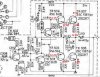
The voltages are shown on the schematic.
View attachment 1898937
15.8 volts on the base of TR504/604
15.2 volts on the emitter of TR504/604 and the base of TR507/607
14.6 volts on the emitter of TR507/607 and the collector of TR508/608 (only about 10 mV dropped across R524/624)
14.0 volts on the base of TR506/606
14.6 volts on the emitter of TR506/606
0.6 volts on the collector of TR506/606 and the base of TR508/608.

Base of 508 is 0.58
Base of 608 is 0.26
 
Yes, a blown fuse will not affect the dial lights. The fuse is in the transformer secondary that supplies operating voltages to the receiver/amp, but the dial lamps are not included in that section.

TR604 base 14.35
TR606 base 12.75
TR608 collector 13.39
TR604 base to output line: 14.35 - 13.39 = 0.96 volts. Low, should be closer to 1.2 volts
TR606 base to output line: 12.75 - 13.39 = -0.64 volts. Good


And for comparison
TR504 base 14.17
TR506 base 12.27
TR508 collector 12.95
TR504 base to output line: 14.17 - 12.95 = 1.22 volts. Good
TR506 base to output line: 12.27 - 12.95 = -0.68 volts. Good

This is making more sense. The voltage on TR604 base is low, yet the output line is higher than the good channel. Interesting.

Couple more measurements. Please measure:
TR507 base
TR507 emitter
TR508 base
TR508 emitter
 
Yes, a blown fuse will not affect the dial lights. The fuse is in the transformer secondary that supplies operating voltages to the receiver/amp, but the dial lamps are not included in that section.


TR604 base to output line: 14.35 - 13.39 = 0.96 volts. Low, should be closer to 1.2 volts
TR606 base to output line: 12.75 - 13.39 = -0.64 volts. Good


TR504 base to output line: 14.17 - 12.95 = 1.22 volts. Good
TR506 base to output line: 12.27 - 12.95 = -0.68 volts. Good

This is making more sense. The voltage on TR604 base is low, yet the output line is higher than the good channel. Interesting.

Couple more measurements. Please measure:
TR507 base 13.62
TR507 emitter 13.02
TR508 base 0.58
TR508 emitter 0.00
 
Sorry, I got myself a bit confused. Which channel has the distortion?

No, my screw up. With the case off and flipped upside down and speaker wires in a tangle I didn't pay close enough attention. The left channel has the distortion. My apologies.
 
No apologies required.. (I just screwed up typing apollogies.. sh*t happens ))... ya know don't lose sleep over the challenge. make notes of what you've done. Clearer brain.
 
Last edited:
So we are looking at the 500 series parts.
Here is where the milliVolts matter. From the previous measurements, it looks like there is about 70 mA flowing through TR507, but none through TR508. Let's confirm that.
Using care not to short anything, measure the voltage *across* R524 - the largish TR507 emitter resistor. You want the red meter lead on one of of this resistor and the black meter lead on the other end of this resistor. Have the meter set to the 200 mV range.

Now do the same and measure the voltage *across* R525 - the largish TR508 emitter resistor.

Are you doing these measurements with the speakers connected? If so, disconnect the left speaker and remeasure the voltages across R524 and R525.

I've annotated the data we have so far:
Annotation 2020-06-16 174338.jpg
 
Checking transistors. 503 and 603 almost identical. Same with 502 and 602.

501 emitter 2.1
Base 2.45
Col 4.38

601 emitter 3.80
Base 3.80
Col 4.56

Useful at all?
 
So we are looking at the 500 series parts.
Here is where the milliVolts matter. From the previous measurements, it looks like there is about 70 mA flowing through TR507, but none through TR508. Let's confirm that.
Using care not to short anything, measure the voltage *across* R524 - the largish TR507 emitter resistor. You want the red meter lead on one of of this resistor and the black meter lead on the other end of this resistor. Have the meter set to the 200 mV range.

Now do the same and measure the voltage *across* R525 - the largish TR508 emitter resistor.

Are you doing these measurements with the speakers connected? If so, disconnect the left speaker and remeasure the voltages across R524 and R525.

I've annotated the data we have so far:
View attachment 1900042


Didn't see this post before I checked those other transistors. Here I go. DMM set at 200m

R524 was 5.2
R525 was 5.0

Is spec 4.7? So, pretty close?
 
501 emitter 2.1
Base 2.45
Col 4.38

601 emitter 3.80
Base 3.80
Col 4.56

Useful at all?
A bit fishy, but hate to get sidetracked. If you select 'Tape' on the 'Tape/Source' switch and feed a signal into the "Tape Monitor In" RCAs, does the distortion go away? In that configuration you are not using TR501/601.
 
Didn't see this post before I checked those other transistors. Here I go. DMM set at 200m

R524 was 5.2
R525 was 5.0

Is spec 4.7? So, pretty close?
The resistor values are 0.47 ohms. The spec for adjusting the idle current is 10 mV across these resistors. That translates to I = E/R = 10 mV/0.47 = 21.3 mA. But those numbers are good for now, they should not be far enough off to create significant distortion. So we may be at a dead end on this trail.
[EDIT] out of curiosity, measure the voltage across R624 and R625 on the right channel.

Try the 'Tape Monitor In' with the tape/source switch in tape and see what it sounds like.
 
The resistor values are 0.47 ohms. The spec for adjusting the idle current is 10 mV across these resistors. That translates to I = E/R = 10 mV/0.47 = 21.3 mA. But those numbers are good for now, they should not be far enough off to create significant distortion. So we may be at a dead end on this trail.
[EDIT] out of curiosity, measure the voltage across R624 and R625 on the right channel.

Try the 'Tape Monitor In' with the tape/source switch in tape and see what it sounds like.

R624-625 were 0.00.

Tape monitor in, set to tape source, very faint sound from left channel nothing from right. Set to monitor left channel now clear and right distorted.

Tape/aux in,, set to tape source, left channel clear and right channel faint/distorted. Set to monitor no sound.

My brain hurts. I guess I let myself get twisted around in our discussions. After I took the measurements with the speakers disconnected I straightened things out a bit with the wires...the right channel has the problem.

Does that explain when I put the cap in backwards it reduced the current in that channel and the distortion faded?(because R624-625 are shot?) Just spit balling.
 
Last edited:
Let me review the measurements we have on the right channel. Looks like no idle current on the right.
 
Voltages on something like this vary a bit, depending on temperature, line voltage, time of day, phase of the moon, etc. So let's get them all in one fell swoop.

TR604
Collector -
Base -
Emitter -

TR606
Collector -
Base -
Emitter -

TR607
Collector -
Base -
Emitter -

TR608
Collector -
Base -
Emitter -
 
Our next step is likely to be removing and testing some of the transistors. Soldering skills up to that? Do you know how to test diodes and transistor with your DMM on the diode range?
 
Voltages on something like this vary a bit, depending on temperature, line voltage, time of day, phase of the moon, etc. So let's get them all in one fell swoop.

Stereo on for over 10 minutes, speakers plugged in, volume at 0 set to tape monitor with nothing plugged in.

TR604
Collector - it just reads 1
Base - 14.04
Emitter - 13.41

TR606
Collector - 0.27
Base - 12.45
Emitter - 13.09

TR607
Collector - says 1 (set to 200m screen goes blank)
Base - 12.81
Emitter - 13.39

TR608
Collector - 12.79
Base - 0.00 (set to 200m it reads 0.45)
Emitter - 0.58
 
Our next step is likely to be removing and testing some of the transistors. Soldering skills up to that? Do you know how to test diodes and transistor with your DMM on the diode range?

Ok at removing and resoldering. Watched some videos and tested a few transistors here so I can get it done.
 
Let's remove TR607 and TR608. You will likely find a mica insulator between the transistor body and the heat sink. These are delicate, and you don't want to break one. If it sticks either the transistor or heat sink, just leave it stuck, don't try to force it off. Use your DMM on the diode range to check the transistors - that will take 6 measurements per device. The meter either the same thing it reads with the leads open, or something near 0.65.

The 6 measurements are:

Red on base black on emitter
Black on base red on emitter
Red on base black on collector
Black on base red on collector
Red on collector black on emitter
Black on collector red on emitter.

So you are looking at each possible pair of pins in both directions. Do this on both TR607 and TR608.
 
Back
Top Bottom