• The move to the new server is done. There are some software and database maintenance updates in process. This has us passing the hat around to help out. We appreciate any donations. Seriously, even a dollar helps. The payment page may be found here - https://www.audiokarma.org/support.html

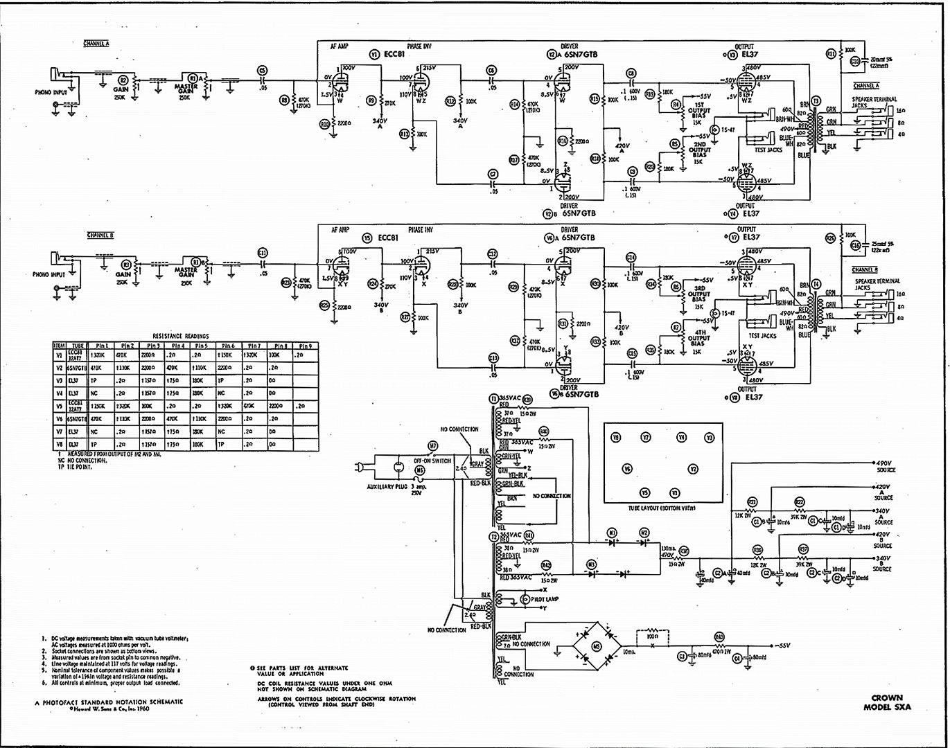
Question on 1959 Crown SXA tube amp power supply, switching noise from half wave rectifiers?? 120hz hum.

sean sweeney

AK Subscriber
Subscriber
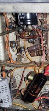
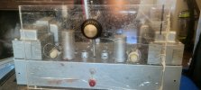
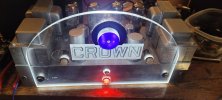
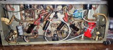
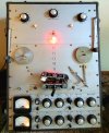
So I got this amp in a trade deal a few weeks ago, and after one issue of basically building it back from scratch, from a blurry schematic from 1960, I still am getting some 120hz hum when the unit is idling, with the inputs shorted. I just replaced the selenium rectifier, and that seemed to help. I had to rebuild the filter cap sections, replace many resistors. I have checked everything, but still audible 120hz hum from this amp. It runs the tubes pretty hot, at 475, and some capacitors are only rated at 450. But I guess what I'm asking is, should I replace the rectifier diodes in this, beings they're from 1959? And they appear to be silicon, or at least look like it. Is that possible in 1959? And could the noise be attributable to the switching noise in the caps? Because although not the neatest wiring I've done, it seems to be correct. With everything within tolerances. I even put two 100uf 400v caps in series to get more reservoir and voltage potential at 50uf, with the schematic calling for 40uf. Still the hum is there, albeit muted. I've searched for noisy output tubes, and preamp tubes, but to no avail. Plus all the tubes are new or NOS, and I've even swapped others in, from working amps to see if that helped. Am I hearing some very old, very used rectifier caps? Everything including the bias supply has been rebuilt. Just wondering if anyone has the experience on this one to suggest if the switching noise would still be audible. I did a little work on the bland cosmetics. Lol. As it had to be the most austere amp I've ever seen. And yes, I disconnected the LED's when hunting the noise down.
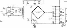
Also, as I look at the schematics, it shows two half wave rectifiers, one for each power tyranny. So halfway rectifyers will basically make more noise right? Is there a reason that these are half wave? Or is there a reason I can't go full wave with these? Are these diodes actually the ones they were making in 1959? Are were they replaced later on? And might that be the reason for the noise which seems like switching noise? Basically one answer could probably satisfied this whole series of questions. Thanks for any help!
 

Attachments

  • Screenshot_20240327_114058_Gallery.jpg
    Screenshot_20240327_114058_Gallery.jpg
    103.8 KB · Views: 134
  • 20240321_154839.jpg
    20240321_154839.jpg
    91.3 KB · Views: 118
  • 20240324_063257.jpg
    20240324_063257.jpg
    79.2 KB · Views: 108
  • 20240324_063417.jpg
    20240324_063417.jpg
    128.1 KB · Views: 108
  • 20240324_063541.jpg
    20240324_063541.jpg
    135.3 KB · Views: 105
  • 20240324_184726.jpg
    20240324_184726.jpg
    33.4 KB · Views: 109
  • 20240324_181147.jpg
    20240324_181147.jpg
    93.5 KB · Views: 110
  • Screenshot_20240326_131104_Reverb.jpg
    Screenshot_20240326_131104_Reverb.jpg
    121.2 KB · Views: 124
  • Clipped_image_20240318_233606.png
    Clipped_image_20240318_233606.png
    648.8 KB · Views: 131
Register to hide this ad
120hz is power supply, but imbalanced output tubes will do this too. The output tubes pull power very early in the supply so its fairly dirty. It relies on equal current draw on each side of the output transformer to cancel it. If you haven't set the bias on the output tubes yet, do that and see if it shuts up.

Its not half wave, this is a classic full wave grounded center tap config. Exactly the same as it would be with a vacuum rectifier, just with solid state parts.

also if the original HV rectifier was selenium, replacing it with silicon will bump the voltage. I see a resistor between the output of the rectifier and the first cap. You can simply bump that resistor to restore the high voltage to where it belongs. Confirm the heater voltage while you're at it though, all of those B+ numbers will be made with the heater supply at 6.3 vac. Higher line voltage skews it, but incorrect output tube bias skews it too.

if you have 475v on a 450v cap, replace it with at least a 500v cap or its going to puke sooner or later.
 
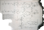
Better schematic, and this is the complete Sams


looks like its calling for 490 volts at the first cap, so that needs to be at least a 500v part and I'd prefer 600 since the initial voltage spike before the output tubes heat up is going to be considerable.

I don't know precisely what its expecting for bias at the tubes, but making some assumptions based on the 130ma figure on the power supply, having each tube running around 40ma doesn't seem unreasonable. That would account for 120ma of the total, and 10ma for the remaining tubes isn't too bonkers. Looks like you'd need to plug an ammeter into the test jacks to do that.
 
Last edited:
I uploaded the schematic. Click on the image to enlarge.

Crown_Model_SXA.jpg
 
Did you change the bias supply's filter caps, too? C3 and C4. Note the reverse polarity on the caps.

Thanks!
 
Last edited:
oh, realized I ran out of fingers when counting stuff. Make that 30ma per-tube, because 30x4 = 120, not 40x4. Derp.

30ma * 490v = 14.7 watts of plate+screen dissipation which is a very easy life on a set of EL37 tubes.

See what coffee will do for you?

also I confirmed my guess, the entire front end uses 11.6ma, or 5.8ma per-channel so 10ma as a guess wasn't too far off.
 
I'm going to try some other power tubes now, though I tried that recently. In the last few days I've replaced the bias power supply, with a modern silicon rectifier. To answer the question, yes I replaced the bias supply caps, two of them at opposite sides of the board the original caps were 80uf at 150v, currently I have two 100uf (the same as the schematic, one rated at 350v, the other being a can, that I wrapped with insulation, as is the practice I've usually seem with the cans, that since it's a negative supply, the cans are typically insulated from the chassis). The bias supply seems to be fine now, though I don't think it was originally the problem anyway. I also took 2 full wave bridge rectifiers and hooked them up the way they would be used in this scenario with a center tap as these do.. I basically hooked the summed ac leads (one from each tranny), summed after the 15 ohm 1 watt resistors and connected to the negative terminal of the bridge rectifier. This would give it two instances of two diodes going forward, to the positive terminal (i figured it wouldn't hurt maybe a little less loss, less switching noise and higher rating). I used fast switching modern bridge rectifiers from a very large power amp that I parted out a while back, both rated well over a thousand volts. This made the hum slightly less, BUT still not gone. And since then I've quadrupled the.
Capacitance reservoir, by putting two 100uf 450, caps in series (50uf at 900) and added another on the other side, of two 80 uf clusters of 10uf caps at 450v, in series, so 40uf at 900. The bias supply has test ports, and they connect to these 47 style bayonet bulbs in the front, which light up when the bias is low, or when overdriving the amp, but I'm thinking of removing all of that, as I don't like all of those wires crisscrossing the amp with the potential to pick up noise or worse.

The bias supply according to the schematic should be -55vdc, which it is sitting at comfortably and steadily.

I have noticed that when I put a test probe on one of the bias points after the resistor that on one tube it makes a bit more noise when the probe is used. And it seems to affect the overall hum level. That initially when I grounded the inputs to make sure there was no. R f or hum coming from the inputs, It seemed to make the hum louder!! That seemed like a clue as well. Though i'm not sure what it would be a clue of? I know it's got good power going to it. I put a three prong cord on there, Which I kind of worried about because it wasn't designed with a three prong, But took it upon myself to make the chassis ground and everything in the amp to default to chassis ground now that it is indeed grounded. I have noticed no ground loops from my a c sources, having used many different ones to be sure... When I pull the preamp tubes, a lot of the hum disappears. I'm going to get my scope out and scope. The actual power going to them and in different locations to see if it's still putting out some ripple. One thing I noticed early on is when I wired some of them incorrectly, It made the hum a lot worse... That maybe the current demands of the power section had something to do with the ripple getting through to the preamp. Is that would be the case what would be the solution? Isolating the power supply more? Possibly separate power tyranny for the preamp? I think that maybe it's just a little too much current demand causing the 120 ripple... That if there were a second power supply for the preamp and driver tubes, What I have here is probably exactly perfect for the power tubes, But not necessarily the preamp. How do you or how would you go about? Isolating the preamp power supplies from the current demands of the power tubes?

I think ive addressed every possible issue... but now I'm wondering if the proximity of the power supplies and output trannies are maybe to blame, as they are literally butted up against each other. Could that be the issue? I'll post some pics in a few. I put another 8 hours into this thing yesterday, adding the two supplies, and other details. Thanks for the input on what this could be. I'll switch the tubes right now, or at least the two I didn't buy together new.
 
Last edited:
oh, realized I ran out of fingers when counting stuff. Make that 30ma per-tube, because 30x4 = 120, not 40x4. Derp.

30ma * 490v = 14.7 watts of plate+screen dissipation which is a very easy life on a set of EL37 tubes.

See what coffee will do for you?

also I confirmed my guess, the entire front end uses 11.6ma, or 5.8ma per-channel so 10ma as a guess wasn't too far off.
Your math skills are a bit over my head! Lol. My deduction at this point Leads me to think that the current demands of the power tubes are causing the hum in the preamp tubes. I think the majority of the noise is emanating from the preamp and driver, which makes sense, but there is zero hum virtually when they are removed.

Is there a way to isolate the power supply more to the preamp tubes, ad more capacitance or would that help? I tried last night with a filter capacitor touching the leads of the preamp tube capacitors together with the other and no difference was heard. Or might I simply try to Introduce a separate power supply for them? Just curious because I'm thinking that's might be the problem. Or the fact that the power transformer and output transformer are literally butted up against each other. I'm gonna try some fresh tubes right now. Even though I tried that earlier, I've done a lot of work since then. New rectifyers on both networks, The power supply and the bias. So that's been completely eliminated.
 
don't throw huge capacitors at it. this wouldn't have hummed excessively with the original value parts, and putting huge ones in there is going to torture the transformer with high peak currents.

also the high voltage supply does not use bridge rectifiers. You need individual diodes for this. If you're aiming for overkill, a total of four 1kv 1 amp parts (1N4007) is all it needs.

The bulbs serve as an overdrive indicator and a fuse in the event of something bad happening. I'd leave them. That whole circuit is low voltage DC, it won't pick up or emit hum.

Did you bias the tubes correctly? If the current isn't equal its going to hum.
 
Well, the power supply as it is now isn't really overkill. It's the recommended capacitance, only higher voltage.
The bias is dead even on all the power tubes. Do we know this amp was dead quiet when new? Just curious because this is a rare early version from the 50s, With no tag on it saying it's an SXA, though certainly is what would have become that amp if it wasn't already. The diodess in their original orientation were three large diodes per side (the way it was here originally), accommodating two ac leads, one from each tyranny, a total of four leads, on two sets of diodes. Hooking up the bridges I used, I hooked each two AC Leads to the negative terminal, which means they would connect to two identical diodes both going forward, but in two sets. I think that is closer to what the schematic is showing than having three diodes in series, with probably the same desired result as the voltage was nearly spot on, with the fifteen ohm resistor it had the expected output... As it's only using two resistors in series (in two sets), But the load is split between two sets of them both doing the same thing. I thought that would be a no brainer. And I have two of these bridges, So they're basically doing what the schematic is illustrating, two diodes in series, And the only reason that they probably wouldn't do this back then is redundancy or the bridges would not be available, or be cost effective. I mean, I don't think I really going outside the functionality of the schematic at all, have I?
 
Last edited:
I mean I haven't done anything with the bias circuit yet. I keep a fuse in it at all times, and use a current limiter until I see what looks like success. I also haven't used the LED array I have on it, just to be sure that wasn't causing the hum. The only reason I used as many capacitors is because they were only rated at 450v, So I doubled up twice and put them in series... Same capacitance as the schematic requires, but double voltage. Also I've heard that doing that lowers the ESR values.
 
I don't mean to seem overly confident, if I'm missing something basic, I would like to know, I was just trying to legitimately get the correct values as stated in the schematics, something that this amp, which was stock, didn't have, but likely they had reasons for that.
 
I'm curious now, how to isolate the preamp tubes more, within the same power supply, if that's the issue. Ok. Changing the power tubes now. Also I think some of the voltages on the preamp tubes may be a little high.
 
Just to clarify, I used single diodes, basically, by picking the place to put the wires in the bridge. And I wasn't aware of the center taps when I first wrote this, hence my dumb comment that it was half wave. I'm not super experienced in classic tube rectification, but I'm learning. After I wrote that it seemed crazy to me that with the really nice components that they would have opted for half wave. They only full wave rectifiers. I knew of used just the two ac leads and no center tap.... I took a refresher course online here and figured out that it is indeed full wave. So... Re-learning, learning... lol. After that I had the single diodes, but looking at the schematic, it seemed just as prudent to leave the bridges in and just tap them as two diodes in series... I guess what i'm curious about now is why they use Two in series, Or three originally, as opposed to the schematic. Was that because the diodes were not highly rated enough back then? I'm thinking I can get by with just one where they had 3 in series before? Meaning less voltage drop and potentially less noise ( I have nothing in my knowledge base that tells me maybe less noise, this is just hoping).
 
Pull the 6sn7 tubes. That will give noise just in the output stage.

When you say the output tubes are even, what exactly are you measuring?
 
Yes, I
Pull the 6sn7 tubes. That will give noise just in the output stage.

When you say the output tubes are even, what exactly are you measuring?
Yes, I did that many times and still had hum, although quite less. With all the work I did this week it WAS getting better... but I did it again tonight and now there was only one side humming. Progress... so as a fluke, I tried messing with the bias and BAM... even though all the bias points were exactly -55v this tube wanted exactly -50. No matter what tube was in there. But with that tube at -50, the problem went away everywhere.
Any ideas? The schematic calls for -55. And if I lean it out anymore than -55 on the other tubes, they hum. I checked the voltages, all pretty much identical. I did notice that one of the high voltage leads on that tube had been changed out at some time. But the good news is it works like this, with no hum!
But i'm still curious as to why. If anyone has any clues. Thanks for the help!

Oh and I don't think I said any of the tubes were mismatched, I wasn't sure on a couple but I don't think there were... If I said so it was a mistake.

Also i'm not sure I mentioned it but I think I took pictures... I don't have the EL37's in this, obviously. They were toast when I got it.
 
I'm going to inspect/replace that iffy new wire on one of the high voltage leads on the tube that wants -50... if that doesn't even it up more, I'll just call it "close enough "...
 
Don't measure the grid voltage, it doesn't matter. measure the current flow through the tubes. Thats what I mean about equal. Go for 30ma at the test points. Going to need to make an adapter to fit the plug, or just eliminate the test points and put in 10 ohm resistors. Set for 300mv across the resistor on each tube.
 
But I guess what I'm asking is, should I replace the rectifier diodes in this, beings they're from 1959? And they appear to be silicon, or at least look like it. Is that possible in 1959?
I have an RF amplifier from the 1950s that uses silicon diodes in a bridge arrangement to produce 1,500V at 1A (six 800V diodes in each leg). No reason to replace components like these unless they fail outright.

Gonset GSB-201 PS.jpg

Jack
 
Last edited:
I have an RF amplifier from the 1950s that uses silicon diodes in a bridge arrangement to produce 1,500V at 1A (six 800V diodes in each leg). No reason to replace components like these unless they fail outright.

View attachment 3163169

Jack
Ok, interesting, so multiple diodes will yield a higher voltage? I wondered about that, since you measure diodes by the voltage loss, correct? I still don't think it was a bad idea, or costly fir that matter, since this thing had crazy hours on it. And I couldn’t find anything definitive on whether diodes from that era had more switching noise. But thanks. I've got a much better handle on this part of the power supply. Nothing is really that complex with the theory of operation in these, apparently, but being able to visualize it is valuable to me. And I think this is the first time I worked this long on something without a minor zap. Lol. One-handed rule withstanding. Lol.
 
Back
Top Bottom