• Please note that Audiokarma will be offline briefly for updates early on Monday morning, September 28th.

Question on 1959 Crown SXA tube amp power supply, switching noise from half wave rectifiers?? 120hz hum.

ok that makes more sense.

so you're meaning make it a dual mono amp without a shared high voltage supply.

If the transformers are the same there is no reason you couldn't, but fair bet the reason they didn't do that initially is that it doubles the parts count for the power supply. Each channel needs its own rectifier and power supply caps. Diodes are cheap now but not so much in the late 50s. Caps are smaller now but still not tiny.

There would be some other tweaks, basically with half the current load, the resistors between the power supply caps would end up double the value to maintain the same voltage drop. All very possible to do provided you have the space to install the caps without it just being a congested mess under the hood.
 
FWIW, Just a thought, is there any metal plate to secure to the bottom of amp`s chassis to complete the amplifier`s shielding for good external hum/noise rejection ?

I would encounter benches electrical wiring, fluorescent lighting, ect. induced hum/noise in high gain guitar amplifiers, so in the early nineties I acquired an 1/8" aluminum plate wide and deep enough to cover any tube amplifier brought to me to cover any chassis while on the bench upside down to duplicate the amp`s shielding while it was mounted in it`s cabinet so not to waste time chasing external sourced EMI hum/extraneous interference noises that would disappear when the high gain tube amp was returned to it`s cabinet.
If not in place, something to consider, as it can make a considerable effect.
 
^^ true, sometimes the bottom really makes a difference.

Also why I was confused when you asked about splitting the power amps, there are some commercial sound amps that are basically 2 channels on a common chassis, but they can have the input and output tied together to produce a single channel output that is twice the wattage. I thought maybe thats what you were dealing with on these. The Bogen MO-200A is one of those, two MO-100A amps on one chassis with a common power supply. Stock its rated for 1 channel at 200 watts of output, but with minor effort it can be 2x 100 watts. Or if you have the MO-100A amps, you can take a pair of them and connect them together to make a single channel at 200 watts of output. I have a pair of MO-100A modified per Dave Gillespie to not use tubes I can't get. They have been my main amps for years now. I briefly considered rebuilding them onto a common chassis as a dual mono, each with it's own power supply but it would have been entirely too heavy. 100 watts of tube power is a pretty solid lump of gravity, 200 watts is just obnoxious.
 
Sorry, a little late to this thread and I haven't read all of it. It's a bit odd in my experience tho have two power transformers in parallel but not a concern if they are matched. However, are the two CT red/red-yel wires connected to the same point?
 
^^ true, sometimes the bottom really makes a difference.

Also why I was confused when you asked about splitting the power amps, there are some commercial sound amps that are basically 2 channels on a common chassis, but they can have the input and output tied together to produce a single channel output that is twice the wattage. I thought maybe thats what you were dealing with on these. The Bogen MO-200A is one of those, two MO-100A amps on one chassis with a common power supply. Stock its rated for 1 channel at 200 watts of output, but with minor effort it can be 2x 100 watts. Or if you have the MO-100A amps, you can take a pair of them and connect them together to make a single channel at 200 watts of output. I have a pair of MO-100A modified per Dave Gillespie to not use tubes I can't get. They have been my main amps for years now. I briefly considered rebuilding them onto a common chassis as a dual mono, each with it's own power supply but it would have been entirely too heavy. 100 watts of tube power is a pretty solid lump of gravity, 200 watts is just obnoxious.
Yes, i have literally tons of old wrecks here and found some sheet steel to complete the chassis. It could have been from other things as the tubes i had were matched and to the last comment on here, yes, the power supplies are connected together for the B+ on the power tubes. And likely I'll keep it that way. I think there were other factors making it noisy before, like bad sockets or bias pots.... it was for these reasons I decided on a total rebuild. Hoping there are no issues with OT's either, as it had so much use.
 
Output transformers are usually not a problem, though some were wound with too-fine wire and fail. More often they go bad from excessive abuse like bad caps causing the tubes to be glowing red and just left that way for a very long time. I had one bad one that was construction related. The wire laid right against the lamination stack and eventually just burned through the varnish and shorted. It should have had a layer of insulating paper between the wire and the frame. It ohm checked fine, but at about 200 volts it would arc and spark.
 
Ok, so I finally rewired this thing, and made the jump to dual monoblock, like I think it should be. However, the channel that was weak before the rebuild is STILL VERY WEAK.
Since this has screen taps, I assume this is ultra-linear? So I think the output tranny on that one side was cooked over the long previous life. It has a constant hum, even when biased correctly and has half the output of the other side. Voltages are spot on, now... though the bias pots i ordered new are already falling apart... luckily, when i separated the two bias supplies, they pretty much came out with the ideal voltage, at negative 55-60v... the bias lights on the one side light up from wattage, and also high mids seem to also trigger it an meager wattage. I hate to say it, but I think this may need an output tranny... and since the numbers on this one don't bring anything up on searches, I'm wondering if I should put two in, so the outputs sound the same.
The hum issues are gone, aside from the bad side... any suggestions on what to get? I'm really wanting to hear this after so long! Lol.
I also made a video of the issues with the bad side. I pulled the tranny to test, but no surprise it tests ok with the meter... I think this is a matter of phase, internal capacitance and possibly uneven response...


Attachments

  • 20250726_003944.jpg
    20250726_003944.jpg
    126.2 KB · Views: 0
  • 20250725_022109.jpg
    20250725_022109.jpg
    79.3 KB · Views: 0
  • 20250725_022117.jpg
    20250725_022117.jpg
    95.3 KB · Views: 0
  • 20250725_022101.jpg
    20250725_022101.jpg
    90.7 KB · Views: 0
  • 20250724_045827.jpg
    20250724_045827.jpg
    116.8 KB · Views: 0
I think this scrubbed my video link.
Let's try....

youtuXbe/kOP2phqjNK0?si=jXwPHA2Vbxflkx4F

The link above should have a period for the first "x".
 
Two clues its a bad output, assuming plate and screen voltages are good

Power output will measure way below normal

The output stage will draw excess current when trying to pass signal. Idle current will be normal. Compare to the working channel

Final confirmation, switch them channel to channel. If the problem moves with the transformer, you have your answer
 
Thanks! Yes, I've done all of that. The problem followed the OT... and what I'm trying to do now is figure out if I can remove the screen taps on these and use the OT as a non-ultralinear output. Apparently the ultra linear output Transformers develop quirks such as distortion and Noise that comes from a kind of developed internal capacitance. These quirks typically come from non-standard use or abuse, lack of proper maintenance over a long period Etc. But apparently does not render the output UNUSABLE, if the ultra-linear taps are terminated, and screen power supply provided... it just makes it more like a guitar amp. A little bit gainy and capable of overdrive. However I've not seen this done with and amp that had been wired Ultra linear before this. So I'm just trying to figure out what my next move is.


Two clues its a bad output, assuming plate and screen voltages are good

Power output will measure way below normal

The output stage will draw excess current when trying to pass signal. Idle current will be normal. Compare to the working channel

Final confirmation, switch them channel to channel. If the problem moves with the transformer, you have your answer
 
The video I posted showed a lot of power being consumed by the OT, as the light bulb was like a strobe light!

Two clues its a bad output, assuming plate and screen voltages are good

Power output will measure way below normal

The output stage will draw excess current when trying to pass signal. Idle current will be normal. Compare to the working channel

Final confirmation, switch them channel to channel. If the problem moves with the transformer, you have your answer
 
you can unhook the screen taps and run it in pentode mode by connecting the screens to a spot in the B+ supply, but if the transformer is bad thats not going to fix the problem. Transformers don't develop capacitence problems or any of that as a matter of course. They basically work perfectly normally, develop a short between windings, or go open. No idea where you may have read that other nonsense, but its nonsense. Bad transformers are bad transformers and unhooking the screen taps doesn't make them usable again.

if you replace it with anything other than an original, you'll want to change both so its matched and its going to need some re-tuning of the feedback bits to make sure its stable.
 
you can unhook the screen taps and run it in pentode mode by connecting the screens to a spot in the B+ supply, but if the transformer is bad thats not going to fix the problem. Transformers don't develop capacitence problems or any of that as a matter of course. They basically work perfectly normally, develop a short between windings, or go open. No idea where you may have read that other nonsense, but its nonsense. Bad transformers are bad transformers and unhooking the screen taps doesn't make them usable again.

if you replace it with anything other than an original, you'll want to change both so its matched and its going to need some re-tuning of the feedback bits to make sure its stable.
Cool. Thanks for your patience. Rest assured I'm being very careful and respectful of what I'm doing.
I had a replacement transformer here for a leslie model 25, a non UL one, that seemed to be a good fit, as it was made for high voltage p-p 6L6 output, in the same wattage as this one... I'm making another node for the screen supplies of the EL37'S, coming off the main power node.

I wanted to separate this node as much as possible, so I read that 1000 ohms is typical for their supply, and I am also considering adding a 10uf cap for each. Using a standoff up at the main can. The multi cap can was as close as i could get to the original, rated at 500v with a bit more filtration, which was fine, since the power supplies with modern components were coming out a little on the hot side.

I split this into a dual monoblock, as mentioned, and on the side which is still stock transformers, the power goes through a single high power rectifier diodes for each AC lead and combined before a 250ohm 5w resistor to get a near perfect 488 volts. Then, going into a 40uf and 20uf, before headed to the center tap. Then the nodes for 12kohm/20uf 420v (driver tube) and 39kohm/20uf source for the input 12at7/PI tube. This differs, but i think is more filtered than the original, which combined power supplies for mains, now separated into the one just described, using a 500v 40/20/20/20 can on each side. And now on this side, adding the supply for the screens. I was thinking that the 1k resistor before the 10uf 500v cap would keep it clean sounding. I've already gotten a good idea of the NFB loop, using a 2 meg wire wound pot and mica cap... and i may convert the other side, as you mentioned, and as I thought might be necessary before that, if using this for hifi use. I just had a fellow contact me with another one of these, so this one is now destined to be a nice instrument amp, so a difference in tone between channels may not be necessary. Indeed, it may be changed to EL34/6550 OR 6L6'S to reserve the el37 tubes for the hifi unit.
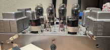
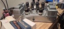
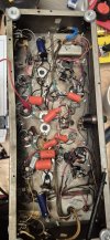
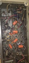
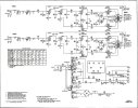
What I'm asking is re: the screen resistors... is it advised to filter the node up at the can and put the resistor directly on the pin for the screen? I was thinking that resistors first, then a 10uf cap for each node running to the screens. Sorry if my posts are a bit meandering... I try to wrap my head around the reason for each action; thinking of the why and mechanics behind these methods. Thanks again. Pictures of the build currently, the NFB caps/resistors are the wires hanging out. I've insulated nearly every hot wire in the new build with shrink tube, and grounded the chassis. Also adding the original schematic. It realky looks like they just shoved their 30w amps into a single chassis, likely the case, which made it a no-brainer to separate them and improve their sound.
 

Attachments

  • 20250802_144053.jpg
    20250802_144053.jpg
    99.3 KB · Views: 2
  • 20250802_144047.jpg
    20250802_144047.jpg
    99.8 KB · Views: 1
  • 20250802_144059.jpg
    20250802_144059.jpg
    55.9 KB · Views: 2
  • 1000028749.jpg
    1000028749.jpg
    117.7 KB · Views: 2
Last edited:
Just wanted to say thank you for all the help on this! The output transformer was indeed bad on this one. I was reasonably sure from the start, but it seemed so unlikely, BUT, given the extreme age, extreme use, dubious storage, the fact that the chassis, once a chrome plated beauty was dark brownish green when I found it and the original tubes all crisp except for one... it was a learning adventure! And there was a guy that saw my suffering from afar and had another one! and his wasn't in NEARLY as bad of shape! So I traded him a nice subwoofer and he mailed me his SXA... and now I have a very nice one that works and the other is performing duties in the band... with a hammond transformer replacing the original and NO NFB... lol... pulling the NFB on this was just the thing to let it all hang out as an instrument amp! which it's also awesome as! The new one I've gone through quickly, recapped, re-built the diode supplies, put a bridge in the bias supply and separated the main power supplies quickly and easily... so it sounds like it should! took me all of three hours! So I definitely learned a LOT... just like my first car, a plymouth volare... with so much blowback it was blowing oil out of the dipstick hole, taught me a TON about cars... by having to FIX all of it! Digging this new amp a LOT... the bias supply came up a little short, so I had to reduce the resistor in the supply... but once all of those tubes were gettting the right amoung, they cleared up and made some incredible sounds! a full quartet of EL37's, NOS... they survived! lol The control plate for the amp was smashed in the mail, but I'll either remove it like the last one, or straighten it out. Right now I'm rearranging the studio accomodate the. new tube amp and some mastering stuff... what a sound!
 
I have a pair of amps with similar story, except had crusty one had good iron and donated to the nice clean one. I built another amp in the rusty chassis with different transformers and much more available tubes. Original runs 7355, and i have a good spare set, my new build runs 6L6, which are probably the most available tubes on the planet.
 
Back
Top Bottom