
That's the 1k resistor, for grid stopper I believe, to go on the side of the power tubes. The stupid thing keeps deleting my text, so I added it on again in my second follow-up
Do you have a resistor or diode inline with this cap?


That's the 1k resistor, for grid stopper I believe, to go on the side of the power tubes. The stupid thing keeps deleting my text, so I added it on again in my second follow-up
Do you have a resistor or diode inline with this cap?

A question: in what setup would the screen voltage be in contact with the speaker?I would not advise having the screen connection land on the speaker output jack. Being able to possibly get 400 odd volts dumped through the voice coil is a bad idea

Definitely! It should be a DIN jack or a Molex, something not Octal. To avoid any possibility of confusion.If the speaker output jack is an octal, any situation where someone lands the wire on the wrong pin. I just don't like the idea of high voltage even being an option in the event of a simple mistake. I try and stupid proof things to save myself tears later when i screw up.

Thanks, I don't think it was like that in the schemo.... but the output for phase inverter is coming from the outputs. Is that typical? Seemed odd to me. And do you understand the schemo for the heater windings? I'm always a little bit in the dark about the heaters on these... the tubes are 12, heaters... But in variably they seem to be getting six volts.... Is that per heater? Because it is too basic amps or pre amps... And I can't seem to figure out if these are getting both sides used or not, As the preamp level seems to be a single stage.... But then there is no phase inverter tube, But rather the old fashioned PI... So maybe that's getting a side as well of that same tube? As I look at the schematic it looks as though both sides are getting heater... And all of the relative pins are being used... So I'm thinking it does. Use the entire 12at7.... I'm just not sure how to hook up the heaters... 6v on either side and ground in the middle? I actually looked it up, but I didn't get the information that would tell me specifically... I understand what's being said, i'm just not sure in this instance. Mainly because this amp is old enough to to have exceptions to a lot of rules. Sorry if i'm making this more difficult!yeah I wouldnt' really want an octal speaker output either, just too inconvenient. My Rauland-Borg amps used one, it remains on the chassis for hole-fill reasons and I'm using it for the bias test points. The speaker outputs are on a pair of binding posts on the side.


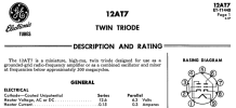
Correct. The input and gain stage duo-triode tube heaters are wired to use 12.6VAC, and the output tube is wired to use 6.3VAC off the same power transformer heater tap.Ow! I used to perform warranty service on Revox, but never had one attack me.
The 12AT7 (like others in that series) can be operated on 6.3V or 12.6V, depending on whether the two halves of the filament are wired in parallel or in series. Most hi-fi gear has the center (pin 9) grounded with pins 4,5 connected together for a 6.3V filament.
View attachment 3188072
Jack

I guess what I'm asking is, the 12at7 in this schematic... is it showing both heaters energized?? I see the pins out, but I don't see pin 9 grounded, and the schematic for the heater shows what appears to be four connections... and in all the pics I took, none of them are showing me exactly the wiring of the heaters explicitly... nor can I find any pictures on line.What they said about the 12a*7 heater stuff
not sure what you mean about the phase inverter. This definitely has one, its the second half of the first triode. This is basically a classic Williamson design. Slightly different tubes than typical but tons of amps were built from this basic arrangement with various tubes.
View attachment 3188230
C5 is the input from the input jack. Pretty straightforward.
The connection to R10 is coming from the speaker terminals through a resistor. This is the negative feedback connection that flattens out response and reduces distortion.
Output from the plate (pin 1) is direct coupled to the second grid (pin 7)
This is called a split load, cathodyne, or concertina inverter depending on who you ask. All the same thing. It has one input on the grid, and an output on the plate and cathode. The output is equal in voltage but opposite in phase so long as the plate and cathode resistor values are identical. Plate side is inverted relative to grid, cathode side is in-phase with the grid.
The 6SN7 sections after this are just a voltage gain stage to drive the output tubes.
It's difficult to read the numbers in the partial schematic in #131 above. It appears that (maybe) pins 4 and 5 both connect to "W" in the power supply, but that won't light that side of the filament. Pin 5 is (maybe) connected to "Z". Looks to be an error.I guess what I'm asking is, the 12at7 in this schematic... is it showing both heaters energized?? I see the pins out, but I don't see pin 9 grounded, and the schematic for the heater shows what appears to be four connections... and in all the pics I took, none of them are showing me exactly the wiring of the heaters explicitly... nor can I find any pictures on line.
I always draw filaments as part of the PS. That's where they belong unless there's a compelling reason to do otherwise (maybe if they were elevated using a nearby cathode connection).Its actually one of my gripes with modern schematics, they draw all that to the tube rather than just drawing a group of heaters out of the way

Ok, so basically, since both sides are being used, wouldn't I use a 6v for 5&6 and then just ground 9 to get them both powered, since 9 is the ground point for both as far as I know?Thats how i prefer them. Shows the connection without making things messy for no reason.

I'm not sure what you're saying here. For 6.3V use, pins 4 and 5 must be connected together. How you apply power between 9 and pins 4/5 is a different issue, because it doesn't matter which node is grounded. In fact, how you maintain the AC zero-crossing at ground potential is also not necessarily relevant to the flow of heater current. Everything could float, including the transformer winding, although that generally induces noise into the tube.run 4&9 with 6v taps and ground 5... same thing basically?