• The move to the new server is done. There are some software and database maintenance updates in process. This has us passing the hat around to help out. We appreciate any donations. Seriously, even a dollar helps. The payment page may be found here - https://www.audiokarma.org/support.html

Question on 1959 Crown SXA tube amp power supply, switching noise from half wave rectifiers?? 120hz hum.

yeah the connection to ground, however it is made, is to dump noise and anchor the heaters to some point so the heater-cathode voltage can be known. Dynaco amps often just used a capacitor with no direct tie to ground at all. Sometimes its elevated by some amount of DC for various reasons, it can be grounded through a center tap, a hum balance pot, a pair of resistors with the junction tied to ground or the elevated DC. Lots of schemes, none of them really matter so far as just making the tube light up.

can also run these things on DC, the heater doesn't care.
 
I'm not sure what you're saying here. For 6.3V use, pins 4 and 5 must be connected together. How you apply power between 9 and pins 4/5 is a different issue, because it doesn't matter which node is grounded. In fact, how you maintain the AC zero-crossing at ground potential is also not necessarily relevant to the flow of heater current. Everything could float, including the transformer winding, although that generally induces noise into the tube.

Jack
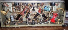
Ok, I just remember that there were just two wires used for the heater connections. So, basically 4&5 together, and 9 will yield the best result, no ground necessary. I don't remember the two being put together is the only thing. I have a pic here somewhere. Screenshot_20240418_222950_Gallery.jpg
 
yeah the connection to ground, however it is made, is to dump noise and anchor the heaters to some point so the heater-cathode voltage can be known. Dynaco amps often just used a capacitor with no direct tie to ground at all. Sometimes its elevated by some amount of DC for various reasons, it can be grounded through a center tap, a hum balance pot, a pair of r20240324_063541.jpgesistors with the junction tied to ground or the elevated DC. Lots of schemes, none of them really matter so far as just making the tube light up.

can also run these things on DC, the heater doesn't care.
So the pic above, here, shows two wires coming in, which looks to be one attached at 9, and some configuration involving 4&5... jumpered together? Looking for another now...
 

Attachments

  • 20240324_063541.jpg
    20240324_063541.jpg
    135.3 KB · Views: 3
yeah the connection to ground, however it is made, is to dump noise and anchor the heaters to some point so the heater-cathode voltage can be known. Dynaco amps often just used a capacitor with no direct tie to ground at all. Sometimes its elevated by some amount of DC for various reasons, it can be grounded through a center tap, a hum balance pot, a pair of resistors with the junction tied to ground or the elevated DC. Lots of schemes, none of them really matter so far as just making the tube light up.

can also run these things on DC, the heater doesn't care.
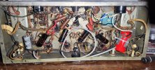
Ok, I think it does look like 4&5 are fused with one lead. And another on 9. In the other pic above.
 
Ok, I see now, the heater transformer taps are shown as x, y abd w,z respectively. And the heater connects read that 5 and 4 go to x, and 9 to y. Same with the other tube and its tranny. And the center tap is grounded. Any idea how I could apply positive voltage in this configuration if I wanted to DC elevate the heaters? Or would that just be negligible? One thing I have to do over is my heater wires... I used stranded wires, and read that the best results will be with solid 20guage wires, tightly twisted. I wanted to check that, as I noticed a lot of care taken and the very heavy solid wire in the original... I would have reused those wires, but for the fact the insulation had deteriorated so much. Ok .. at least that's sussed.
 
solid v stranded doesn't really matter much but the twist helps.

looks like this setup uses a grounded center tap on the heater winding.

1714564956970.png

If you want to elevate the heater somewhat, unhook the center tap connection to ground. Build a voltage divider from the +490v source to ground. I'd probably go with a 470k resistor in series with a 47k, with the 47k closer to ground. Bypass the 47k with an 0.1uf film cap. That should give about +45 volts on the heater circuit. It will make the phase inverter section happier but won't stress the rest of the tubes either.
 
1714566931824.png

Regarding size and solid vs stranded - I used this stranded Belden 9497 (16 AWG) for the filaments/heaters in a single ended build because I have a lot of it and the amplifier is noise free.
 
I've used 18 awg because I had it. I don't know that the gauge is super critical but you do have to mind the total size when dealing with 9 pin sockets. Trying to get 2 sets of overly-fat wire through one of those terminals so it can feed to the next tube in the chain can be a chore. 16 might be pushing it, I know two sets of 18 can be a little difficult.
 
I've used 18 awg because I had it. I don't know that the gauge is super critical but you do have to mind the total size when dealing with 9 pin sockets. Trying to get 2 sets of overly-fat wire through one of those terminals so it can feed to the next tube in the chain can be a chore. 16 might be pushing it, I know two sets of 18 can be a little difficult.
18-gauge is fine, just for the reasons you stated. I like to determine the length and geometry and twist it on before putting the socket onto the chassis, if possible. It's easier that way.

I like single-stranded copper. It holds the twist better than multi-stranded.

DSC07455.JPG
 
Last edited:
what I usually end up doing is chucking one end of a length of wire in the drill and twisting the whole thing up, then cutting it to lengths as needed. Depends how much I've got and how much I need but the lamp ballast wire I often use for this I get in roughly 2 foot lengths.
 
what I usually end up doing is chucking one end of a length of wire in the drill and twisting the whole thing up, then cutting it to lengths as needed. Depends how much I've got and how much I need but the lamp ballast wire I often use for this I get in roughly 2 foot lengths.
I also use a hand drill. Very slow speeds.

Cloth-covered, single-stranded wire holds its shape the best. I hate that 1970-80-era thick PVC insulated wire. It never holds its shape. Like a bad hairdo!

bang head on wall.gif

VLR_1972_left_side_chassis_rFjYVh5DuvZyzWAN3zLWvN.jpg
 
fluorescent lamp ballast wire stays reasonably well. I have a fairly steady supply from work, the warehouse is full of lights with 2 ballasts each and they go bad from time to time. I just snip the wire off before tossing the ballast. Lots of convenient 2-3 foot chunks of 600 volt wire. Maybe not the best thing but its the right price.
 
fluorescent lamp ballast wire stays reasonably well. I have a fairly steady supply from work, the warehouse is full of lights with 2 ballasts each and they go bad from time to time. I just snip the wire off before tossing the ballast. Lots of convenient 2-3 foot chunks of 600 volt wire. Maybe not the best thing but its the right price.
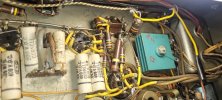
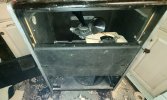
So, my new friend has indeed gotten me some NOS El37's, matched!!! I just have to whip up a little all purpose leslie cabinet, which I have the parts for here... many times over! And BB organ has a handy little box that turns the fast leslie ac motor into the SLOW one as well, so only have to install fast motors. I've used those ones before... Pretty cool idea... It just pulses the ac in a kind of slow sine wav, so the motor bearings don't get stressed, or make noise vibrating against the cab. Check out these tubes! Screenshot_20240513_092545_Message+.jpgScreenshot_20240513_092610_Message+.jpgScreenshot_20240513_092631_Message+.jpg
 
I'll be finishing this up soon here... But one final question and I'm curious about what you think.... Would I be better off in general using the two separate power amplifiers to power each side individually? Or should I hook them up together like they did with the original schematic? It seems like if I use a full wave rectifier on either side I should get proper voltage on each individual side...
 
this is a two channel amplifier. Not sure what you mean.
Yes, but The two power transformers are linked together at the the rectifier circuit to get the b+ used for both sides. I always kind of liked the idea of having two separate amplifiers from the power supply on down.... But in this circuit they are linked together right before the diodes. That is both power transformers combined to get the b+ and I'm wondering if there's any way to have them separate and get the same result. I just got a new phone here but I believe the schematic is here on this post.
 
this is a two channel amplifier. Not sure what you mean.
I had been wondering about that for a while and I didn't know if it was just for a cost cutting measure that they did this or to save space or what the real reason was that they had two transformers providing the b+. If it's the way it should be the way it is now then I'll just leave it. But I thought maybe if I could put a full wave rectifier in there, that it might do the job and have the power supply and everything else in the circuits discreet and separate for both sides..
 
Sorry if my question seems a little bit too elementary. I just ask about these things because on the one hand I don't know if they were cutting costs on this particular design or if it was meant to be like this for a particular reason... Such as space limitations. And I guess it's just the aesthetic, even though only in my mind that this would be the same as two, essentially monoblock amplifiers in a single case. But if it's just something silly and inconsequential then that's fine.
 
Back
Top Bottom