• Please note that Audiokarma will be offline briefly for updates early on Monday morning, September 28th.

Question on 1959 Crown SXA tube amp power supply, switching noise from half wave rectifiers?? 120hz hum.

Are you getting new output tube sockets? Right?

Old worn sockets are the number one cause of intermittent bias supply voltage to the grids.
Yes, I thought about the porcelain ones, but got the other kind, closer to the originals. I want to say micamold, But those are the capacitors from back in the day... Mica something...
 
This is to resist high-frequency oscillations. It comes from the world of radio transmitters. How much a wrapped resistor helps in the audio frequency range (even in the ultra-high audio frequency range) is questionable.

What guys used to do with unstable amps was wrap grid stoppers and plate resistors with thin copper wire (of varying lengths). Sometimes it worked, sometimes not. Sort of like signal lines wrapped around ferrite beads.
So woukd the resistor or resistor coil combo be something you would put in a rebuild?
 
So woukd the resistor or resistor coil combo be something you would put in a rebuild?
Nope. Those are patches for ultrasonic parasitic instabilities. Adjusting the wiring layout usually fixes many of those problems in audio amps.

However, leave whatever wrapped resistor(s) is in the amp in the amp. :thumbsup:
 
Yes, I thought about the porcelain ones, but got the other kind, closer to the originals. I want to say micamold, But those are the capacitors from back in the day... Mica something...
Micalex. In my opinion, those are better than today's porcelain ones.
 
Micalex. In my opinion, those are better than today's porcelain ones.
I've thought so too. I think they have a better heat tolerance... As in the porcelain Can take the heat but they heat up very quickly... Stressing other components around it. The density of the micalex, Means that the whole thing won't heat up as quickly.
 
I've thought so too. I think they have a better heat tolerance... As in the porcelain Can take the heat but they heat up very quickly... Stressing other components around it. The density of the micalex, Means that the whole thing won't heat up as quickly.
Porcelain sockets that are being made today tend to be inferior in quality. Belton Micalex ones are good stuff.
 
I've thought so too. I think they have a better heat tolerance... As in the porcelain Can take the heat but they heat up very quickly... Stressing other components around it. The density of the micalex, Means that the whole thing won't heat up as quickly.
Nothing to do with heat tolerance. It's the poor quality of Chinese metallurgy used in the porcelain sockets that causes issues.
So woukd the resistor or resistor coil combo be something you would put in a rebuild?
If the manufacturer couldn't stabilize it without those components, you're not likely too either. RF oscillations are often intermittent, and they sometimes occur over only a small portion of the wave when the amplifier is driven, and sometimes only under certain combinations of drive and load. This can be exceedingly difficult or impossible to detect without a high quality RF spectrum analyzer. The suppressor you're describing has no detrimental effect on audio signals, and it's cheap insurance to include it in the rebuild.

Jack
 
quite possibly its the bias pots causing the issue. They get dirty and things go flaky. easy enough to replace them.

also why those bulbs are a handy thing to have. Annoying to replace but a heck of a lot cheaper than replacing output tubes.
 
quite possibly its the bias pots causing the issue. They get dirty and things go flaky. easy enough to replace them.

also why those bulbs are a handy thing to have. Annoying to replace but a heck of a lot cheaper than replacing output tubes.
Yes, that's why I come here! And my thoughts as well with the pots... Thank you that even back in the 1950s, That they weren't wirewelled anymore. And the sweeper was probably still a weak point even with about fifty volts over a long period of time... as I imagine the various times it went down for whatever reason those pots took a little bit of a beating.... and one partially vaporized sleeper would make them all suspect, but replacing all the usual suspects is also prudent. Do you think the carbon comp resistors will be ok? None are discolored... They're between the pots and the input (grid, is it?) And are some higher value. And would they work for bias calculations? If so I will probably replace with new metal films to ensure reliable calculations.
 
yeah I really don't know why so many bias circuits were designed with no fail-safe ability. There are several ways to pull it off, but in this sort of setup a single resistor is enough to do it.

I'm not really a huge fan of carbon resistors. They drift badly and get noisy. Measure them and replace anything out of tolerance.
 
yeah I really don't know why so many bias circuits were designed with no fail-safe ability. There are several ways to pull it off, but in this sort of setup a single resistor is enough to do it.

I'm not really a huge fan of carbon resistors. They drift badly and get noisy. Measure them and replace anything out of tolerance.
I like metal oxide resistors in the bias supply. More stable under the heated conditions of tube amps.
 
I just realized the schematics posted earlier for this amplifier don't indicate that either grid stoppers or screen stoppers have been installed at the output tubes. Perhaps that's why the parasitic suppressors were needed. OTOH, no parasitic suppressors are shown on the schematic either. Why is that?

Jack
 
could be a Sams error, or a revision change. Would be ideal to find original Crown docs for this. They may have some more information about any revisions to the amp.
 
could be a Sams error, or a revision change. Would be ideal to find original Crown docs for this. They may have some more information about any revisions to the amp.
Yea, this is the oldest one I've found on line... I've looked all over for an original Crown document. This one is from 1960, and I don't recall their being anything missing from the scheme aside from those resistors I mentioned. So are grid stoppers or screen stoppers a good idea? Any reason why they wouldn't have them in 1959?
 

Attachments

  • sxa-photofact1.jpg
    sxa-photofact1.jpg
    128.2 KB · Views: 11
could be a Sams error, or a revision change. Would be ideal to find original Crown docs for this. They may have some more information about any revisions to the amp.
It's not built into phase inverter, is it? I wouldn't think so, since the resistor and small mica capacitor are in parallel and you can see it labeled in the schematic.
 
Per Wikipedia Crown started building amps in 1959, so its far from impossible they had to learn a few things along the way.

Grid stoppers are generally considered good practice. A 1k at the grid of each EL37 socket won't hurt it a bit though. You want the body of the resistor as close to the socket as possible.

the screen stoppers are not absolutely critical but its also not a bad idea. Modern caps have lower ESR and under the wrong conditions it can contribute to screen arcs in the output tube. Adding 100 ohms or so between the screen and the screen tap on the output transformer will de-tune it and stop that from happening. Its possibly less critical with a lower transconductance tube like a 6L6GC but its another "not gonna hurt" thing. Tubes are expensive, resistors are cheap.

First time I wound up the volume on my Pilot SA-260 after rebuilding it, the 6CA7 (EL34) output tubes flashed. Shut it down and added the resistors, it hasn't done it since and thats been years now.


It's not built into phase inverter, is it? I wouldn't think so, since the resistor and small mica capacitor are in parallel and you can see it labeled in the schematic.
I think you mean the resistor and cap in the feedback circuit. The resistor sets feedback level, the cap is called a "phase advance" cap, its part of the high frequency tuning.
 
Repaste the schematic for convenience's sake. Click on the image to enlarge.
Crown_Model_SXA_(2).jpg
 
Per Wikipedia Crown started building amps in 1959, so its far from impossible they had to learn a few things along the way.

Grid stoppers are generally considered good practice. A 1k at the grid of each EL37 socket won't hurt it a bit though. You want the body of the resistor as close to the socket as possible.
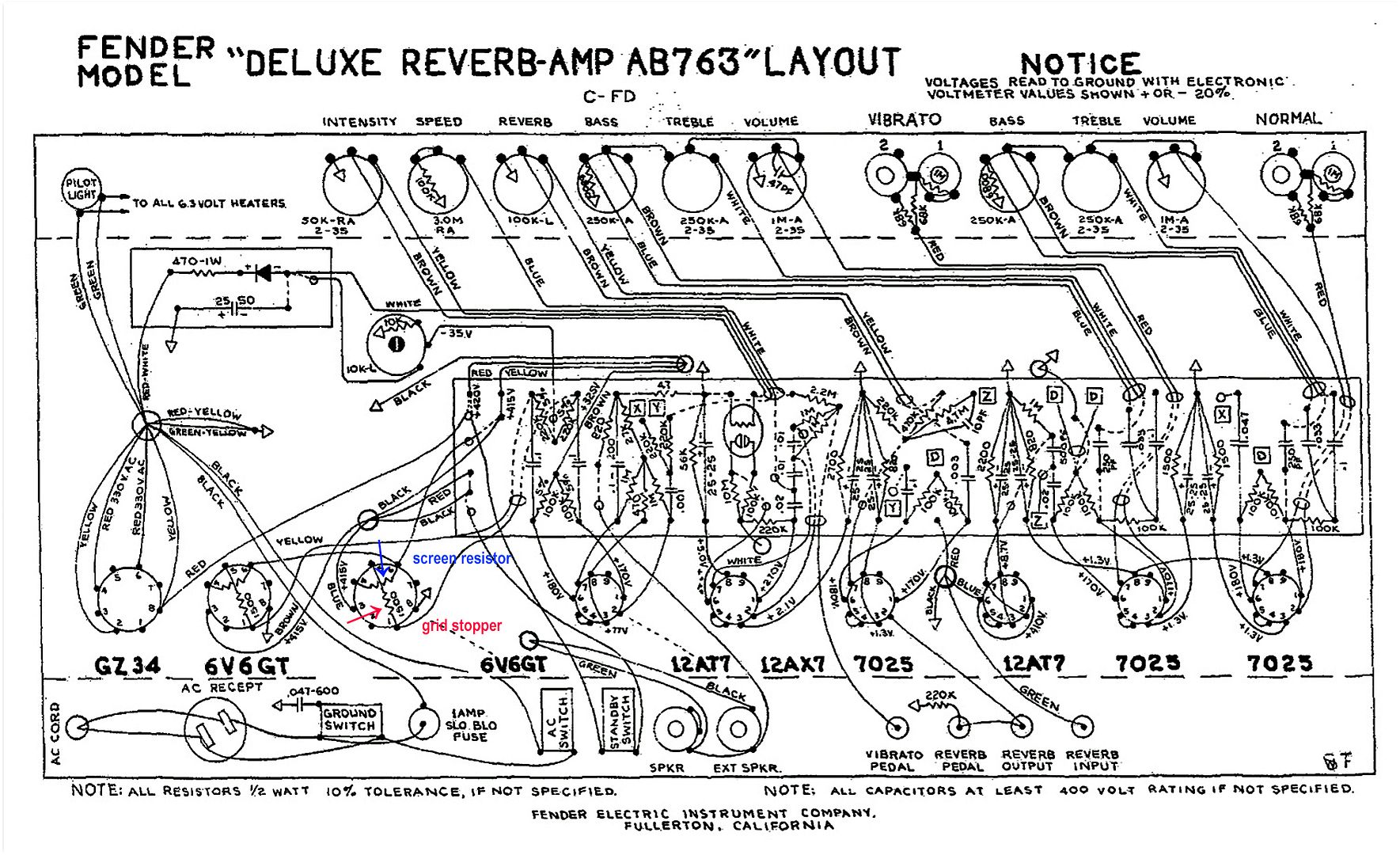
You can solder the grid stopper resistor from the signal grid pin 5 to, say, free pin 1 (then the signal line is attached to pin 1).

Same with the screen resistor. From free pin 6 to pin 4.

That way, the lengths are kept as short as possible.

Photos are of the screen and grid resistors in a 6V6GT amp with the same pinout as the EL37 or 6L6GC.

grid_stopper_-_screen_(1)_bzSmawL2eFBEBTz3pfpCGz.jpg


Deluxe_Reverb_AB763_lay_grid_and_screen_resistors_-_Copy.jpg
 
You can solder the grid stopper resistor from the signal grid pin 5 to, say, free pin 1 (then the signal line is attached to pin 1).

Same with the screen resistor. From free pin 6 to pin 4.

That way, the lengths are kept as short as possible.

Photos are of the screen and grid resistors in a 6V6GT amp with the same pinout as the EL37 or 6L6GC.

grid_stopper_-_screen_(1)_bzSmawL2eFBEBTz3pfpCGz.jpg


Deluxe_Reverb_AB763_lay_grid_and_screen_resistors_-_Copy.jpg
Oh, and I may have mentioned that I don't have the original EL37'S, But I have a quartet of new matched EH Tubes... It's supposedly what the EL37's were souped-up versions of. The actual EL37's were mullards I think, And I haven't seen any other brand of them produced. I'm not sure what the difference is with them. But a pair of them costs around eight hundred dollars... With no mention of matching... I was wondering a couple of things also... I'm buying a quartet of 6550, by EH... And I seem to recall that they actually do work in the same tube socket as a 6L6. To make them work correctly if possible, I'm curious what there would need to be done... Also just the other day. I heard someone talking about using multiple coupling capacitors possibly? To change the voicing of the amp to maybe get more bass? Just curious because i'm thinking that this amp doesn't stay very linear down into the low bass frequencies that you can get nowadays. I have subs here so I could certainly compensate. But I was just curious if there was a way to get these things to thump a little bit. Natural I haven't tried that yet, But was curious if you've heard her heard about that, and whether 6550's might be closer to the EK37 output and overall more like headroom you woukd hear. Thanks for the info. I'll certainly be doing that with this in the rebuild.
 
6550 uses more heater current than a 6l6gc. Dont have something with a large enough screen in front of me to see how they compare to an el37 though.
 
Back
Top Bottom