• The move to the new server is done. There are some software and database maintenance updates in process. This has us passing the hat around to help out. We appreciate any donations. Seriously, even a dollar helps. The payment page may be found here - https://www.audiokarma.org/support.html

Questions on newly acquired NAD 7020

EC1

Super Member
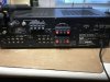
Just bought one not expecting too much since the seller did state no sound/low volume even volume knob all the way to the maximum. Also all RCA covered with rust, selling as parts, not working. After it arrived, the front face does not look too bad, all knobs, buttons there, sticky to operate as expected. Dial lamp out all other lights working. Apparently, the jumpers were missing and I am thinking that might be the main reason no sound. Sure enough, after a pair of RCA cable, the unit comes back to live singing. Some statics and thump at power on and off. Exercising all the controls to loosen them up and apparently this unit probably has been sitting for a while. It looks clean to me other than the RCAs rust. Polish them with BRASSO but only helps a bit. Run it for low to medium volume all day for 8 hours yesterday. No issue experienced other than the power on and off thump. Seems like a good project to fresh it up a bit. Several questions for your help:

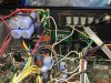
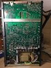
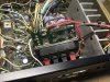
1. I thought it is a version II 7020 by its serial number at the back, “N7219328”. But after I opened it up, it apparently is a version I 7020, no vertical sub PCBs. And further look around see the serial number on PCB board as “N7200201”. So I got a car with engine number not matching chassis number, is this common? I read somehow version I has more issues?

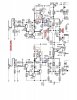
2. Also learned 7020 basically is a 3020 + tuner and 3020 has the issue of the bad caps (C531, C532, C533) on the preamp mute circuit creating the “welcome thump” issue, does that apply to 7020? If it does, where is the mute circuit on 7020, are they C531 and C532 in schematics or somewhere else? Assuming they are C531 and C532 but I seems cant locate them on the board?

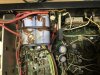
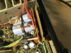
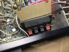
3. Those 4 larger capacitors run horizontally mounting in a vertical board connecting to the speaker terminals look bad to me. How do I access the back side to replace them? Cant tell how is that board mounted?

I am just trying to replace something obvious and go slow to see is it worth to recap? But the more I listen to it, the more I want to keep it.

Thanks in advance.
62D04637-F714-47DC-8484-B328D039D4E7.jpeg 84A311AD-8A1F-447C-AE12-C5124420E0A9.jpeg 69FD0D88-E49C-468F-8DAA-00692173E8FB.jpeg E4161132-44D5-423D-A592-F106DCE48F5C.jpeg 5D923CE3-3FA1-44AC-B656-F1D7407581E9.jpeg
 
Register to hide this ad
Hi there,

0) Answering the question you posted on my 3020 thread. Yes, you can put 3300uF 50V caps here in your 7020 receiver. I wouldn't get too hung up on what brand you use (something reputable though), concentrate on finding whichever ones have the highest ripple rating with a 7.5mm lead spacing. The last 3020 I restored, I used some United Chemi-Con ones Mouser part #661-EGXF500ELL332MM4 but they are out of stock now.

1) I have seen this as well where the serial number on the board doesn't match on the case. Why, I don't know. The issues with the early version were that it used a double sided PCB, and I don't think there was any through hole plating. This is why you will see little pins connecting the top side of the board to the bottom. Sometimes, it's not the amount of components you can place, it's how you are going to connect them all. If you have one of these early ones that's still working, great news! You've countered all the NAD nay-sayers that say their equipment is unreliable. What I would do is re-flow every solder joint inside that thing. By re-flowing, use some wick to take up the old solder, and flow some new stuff. Sometimes, would might see a component wire that looks a like corroded, and the new solder won't stick. Take the time to lift that leg of the component, sand down the wires until they are clean, and re-install it.

2) From the Rev2 manual I have, it looks like they did the muting in another way, centering around Q509 and Q510 switching on the FETs Q511 and Q512. Sometimes, you can't always compare the receiver schmatics with the amplifier. For the 3020, C531-533 do indeed control the muting, but in the schematics you posted, they are part of the line driver/tone control circuit.

3) The four large caps are the ones already spoken about above. The board must be held in with something. Maybe it's one board with the speaker terminals, removing the screws or "push pins" that hold these in will remove the board?

Yes, it is totally worth a recap. The phono stages in these old 1020/3020/7020 pieces are worth the price of admission alone. Pair it with some fairly efficient speakers like some Large Advents, and you'll never run out of volume.

Lee.
 
D468F4BF-8DC9-4EA1-8840-71632DE1E718.jpeg Lee, thx for writing this.
I feel lucky on this Rev. I unit even there are know issues as you mentioned, it is running nice other than the power on off noise and dial lamp out. Tuner has good reception, it sounds excellent for straight 8 hours with no issues. Run warm but not hot. The traces at the back look good with a quick glance.
1. I think, the correct way to tell it is Rev. I vs Rev. II is by its NORMAL main in rca position. If they are at the left side of pre out, it is Rev I. If they are at left side of pre out, it is Rev. II. By the serial number on the case is not 100% guaranteed like my case, unless you open the cover to confirm the serial number printed on the board.
2. Some looking around on the sub vertical board holding 4 caps which seems to be soldered to both A and B speaker terminals and separated by a cardboard material insulator. I did pull those push pins out to release the speaker terminals from the case and pull the whole assembly inward. I can bend the cardboard to reveal the solder tips of the upper 2 caps but not quite sure about the lower 2? They seem blocked by the A terminal and the only way to access them are desoldering them or just A terminal so I can bend the board lower. This seems really tedious, wish someone has done this before and confirm this for me before I going in? I don’t have a lot of experiences and always want to make sure I am doing the proper things. Thx.
E34EE575-DD84-4E3A-833B-F7F716CA5AF1.jpeg
 
With point 2 it definitely looks packed, taking amplifiers is sometimes half the battle.

Take your time, take plenty of photos and notes
 
Also learned 7020 basically is a 3020 + tuner and 3020 has the issue of the bad caps (C531, C532, C533) on the preamp mute circuit creating the “welcome thump” issue, does that apply to 7020? If it does, where is the mute circuit on 7020, are they C531 and C532 in schematics or somewhere else? Assuming they are C531 and C532 but I seems cant locate them on the board?

I'm not overly familiar with the 7020 (I prefer separates) but C533 & C534 are the 2 main caps associated with the muting circuit - but - it's not an identical circuit to the 3020, so I can't say if they're likely to be an issue or not. Does it give a "welcome thump" if you pull the pre-out / normal-in jumpers ?
 
Merry Christmas to all.

With the jumpers (RCA patch cable in my case), there’s a tiny thump right at after pushing the power switch on, then a louder thump about 10 seconds later. Loud thump at the power off as well.
Without the jumpers, only the tiny thump right at after powering up. Almost not audible. No loud thumps.
I just using the mute button to avoid these while I figuring out what to do now.
 
So how to adjust the bias, this is so confusing plus the board is not clearly marked.
1. Where are resistors R659 and R660, can not find them at the front, neither at the back. I assume they are supposed to be at those 4 blob solders location right above R648, 647? The note #6 on the schematic says “short” them after idle adjustment, mine does not even have them at all?
2. If I am going to install the 1k trimmer as per @leesonic to replace the RX1, RX2 (even mine looks like PX1, PX2) there seem not enough space?
3. The output transistors temp are about at 102F at one channel and 99F the other.
Thx.

BEA9828A-BA4E-4875-B146-0E13B93AE991.jpeg 1332E849-A942-4D0D-811F-8BD489019A57.jpeg EA0E43DB-5770-4BDA-9745-B7DAFEB65C06.jpeg 3487F32D-D1E9-480F-99A5-7913256197C8.png
 
On your start-up sounds, I suspect it's a combination of things - some of it's likely down to ageing caps, some to the way the muting circuit operates, and maybe a little also to wear in the ON/OFF switch itself. I'd be interested in how much dc-offset you have at the speaker connections (test as per the manual) ? as well as at the pre-out sockets ? e.g., with the pre-out / norm-in jumpers or RCA leads pulled, measure the DC mV between the centre of the pre-out rca connector and the amp chassis, for each channel, say 2 or 3 minutes after the unit is turned on. It won't solve anything, but may help explain some of it.

Re. your bias Q. - unfortunately, the early SM doesn't include parts location diagrams, so the only way to locate R659 & R660 is to physically 'follow' the pcb tracks / connections versus the schematic, so for R659, start at the collector of Q617 (the collector is the metal case of the MJ2955 itself), and just follow all tracks & wiring that are connected to it; as far as I can see from the manual, there should only be a wire to the -29V supply (coming from the PS board with the 4 big caps), track(s) to Q613(C) and C631, and maybe the R659 resistor (or a location for it). Note - it's not guaranteed that R659 or 660 will be present - they may never have been fitted.

Having said that, and considering your own comment "Tuner has good reception, it sounds excellent for straight 8 hours with no issues. Run warm but not hot. The traces at the back look good with a quick glance" - I'd be inclined to leave the bias settings alone for now, they don't appear to be a problem at the moment. There's little to gain at this point, and a lot to possibly lose.

The earlier NAD models are more of a PITA to work on, as you're already discovering... personally, with this one I don't think there's a lot to be gained from changing one or two parts, not with the way it seems to be running. I'd be more inclined to either enjoy it 'as is' (maybe clean the controls), or go for a complete recap / refurbishment which as Lee says would certainly be worthwhile, especially if it's in good cosmetic condition - but that does involve quite a lot more work & dismantling, and depends obviously on your skill level etc.
 
Last edited:
My plan is always to take it slow, take care of the obvious and see how far I can go.
These capacitors are always the “eyesores” for me. Not quite sure what happened, some sort of corrosion?
9033F8FD-00BE-42A2-9731-F38A1CA7C57D.jpeg
1. Pull off the whole board along with both speaker terminals, score the cardboard insulator to expose the traces and hoping I can poke into the lower legs of the 2 lower capacitors. No luck. Just not enough space.
549E0B4A-CCBA-4947-9659-DBB46B047631.jpeg 90D1279F-6573-46C7-BDFB-EA0102DF3310.jpeg

2. Plan B, remove the speaker A terminals, not knowing how this was connected, just desolder the 4 blobs of solder and a bit of pulling, it came straight off. It does take me some time to remove those 4 solder points. Then bent the cardboard more to expose the lower legs of the capacitors.
8BE0D29A-422A-4E7D-B89E-6C4941F09D15.jpeg
3. Start desoldering the capacitors, not have enough experiences, these solders are just very difficult to remove for me. Don’t know what they are. The sucker does not work, have to use desolder wick or braid multiple times little by little. Able to get the first one off.
F3DFA8BE-86BE-40C3-9A95-018B73982F38.jpeg 382DFEEB-6B66-41F6-A464-E900012306EE.jpeg
4. will continue to remove the other 3 then order parts.
This is it for now.
 
The brown gunk on the capacitors is glue, used to help secure the caps to the board.

If you cannot melt the solder enough to take most of it off with a sucker then you need a larger tip, I use braid to make sure that I've got all the solder off that's connecting the component legs to the board.

Before making an order have a think that generally in these Nad amps the smaller value caps are the ones that have changed value and have high esr.

Also make a plan to replace that piece of card, it was there for a reason.
 
@Goldie99 "I'd be interested in how much dc-offset you have at the speaker connections (test as per the manual) ?"

The left was within 50mv maybe around 15. The left was at 900 when I got it but I was able to adjust it back down per SM, dont remember the exact number though. measuring the preout? Have not done that, probably have to wait since it is taken aprt as posted.
 
The brown gunk on the capacitors is glue, used to help secure the caps to the board.

If you cannot melt the solder enough to take most of it off with a sucker then you need a larger tip, I use braid to make sure that I've got all the solder off that's connecting the component legs to the board.

Before making an order have a think that generally in these Nad amps the smaller value caps are the ones that have changed value and have high esr.

Also make a plan to replace that piece of card, it was there for a reason.

Was thinking about the soldering tip but my cheap soldering iron expand and contract does not allow me to swap them out any more, I think.
The cut out board either will be glued back or to the back side or the case, I think it is preventing some electrical interference or short to the case.
Thanks for the tips.
 
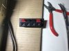
I thought the speaker terminal should have 2 connections at each but this only has one? Is this correct? Thx.
FF6D5010-FC0C-44CD-8163-83D56D17F7DA.jpeg 8A6800CB-1A3E-4A6B-ABB4-8BA93EF4C1BD.jpeg

thought the new ones always come with 2 connection points. Not try to replace them, just curious on the existing ones.
C4BC6B62-F3B1-407A-BC4C-A0C327859995.jpeg
 
Last edited:
Connections differ with speaker connectors, there's nothing wrong with any of the ones you've posted
So if I were going to upgrade to the new speaker post, I just connect the center connector to where the old one is and ignore the side one just leave it there?
 
Hi there,

0) Answering the question you posted on my 3020 thread. Yes, you can put 3300uF 50V caps here in your 7020 receiver. I wouldn't get too hung up on what brand you use (something reputable though), concentrate on finding whichever ones have the highest ripple rating with a 7.5mm lead spacing. The last 3020 I restored, I used some United Chemi-Con ones Mouser part #661-EGXF500ELL332MM4 but they are out of stock now.

1) I have seen this as well where the serial number on the board doesn't match on the case. Why, I don't know. The issues with the early version were that it used a double sided PCB, and I don't think there was any through hole plating. This is why you will see little pins connecting the top side of the board to the bottom. Sometimes, it's not the amount of components you can place, it's how you are going to connect them all. If you have one of these early ones that's still working, great news! You've countered all the NAD nay-sayers that say their equipment is unreliable. What I would do is re-flow every solder joint inside that thing. By re-flowing, use some wick to take up the old solder, and flow some new stuff. Sometimes, would might see a component wire that looks a like corroded, and the new solder won't stick. Take the time to lift that leg of the component, sand down the wires until they are clean, and re-install it.

2) From the Rev2 manual I have, it looks like they did the muting in another way, centering around Q509 and Q510 switching on the FETs Q511 and Q512. Sometimes, you can't always compare the receiver schmatics with the amplifier. For the 3020, C531-533 do indeed control the muting, but in the schematics you posted, they are part of the line driver/tone control circuit.

3) The four large caps are the ones already spoken about above. The board must be held in with something. Maybe it's one board with the speaker terminals, removing the screws or "push pins" that hold these in will remove the board?

Yes, it is totally worth a recap. The phono stages in these old 1020/3020/7020 pieces are worth the price of admission alone. Pair it with some fairly efficient speakers like some Large Advents, and you'll never run out of volume.

Lee.
 
Hi there,

0) Answering the question you posted on my 3020 thread. Yes, you can put 3300uF 50V caps here in your 7020 receiver. I wouldn't get too hung up on what brand you use (something reputable though), concentrate on finding whichever ones have the highest ripple rating with a 7.5mm lead spacing. The last 3020 I restored, I used some United Chemi-Con ones Mouser part #661-EGXF500ELL332MM4 but they are out of stock now.

1) I have seen this as well where the serial number on the board doesn't match on the case. Why, I don't know. The issues with the early version were that it used a double sided PCB, and I don't think there was any through hole plating. This is why you will see little pins connecting the top side of the board to the bottom. Sometimes, it's not the amount of components you can place, it's how you are going to connect them all. If you have one of these early ones that's still working, great news! You've countered all the NAD nay-sayers that say their equipment is unreliable. What I would do is re-flow every solder joint inside that thing. By re-flowing, use some wick to take up the old solder, and flow some new stuff. Sometimes, would might see a component wire that looks a like corroded, and the new solder won't stick. Take the time to lift that leg of the component, sand down the wires until they are clean, and re-install it.

2) From the Rev2 manual I have, it looks like they did the muting in another way, centering around Q509 and Q510 switching on the FETs Q511 and Q512. Sometimes, you can't always compare the receiver schmatics with the amplifier. For the 3020, C531-533 do indeed control the muting, but in the schematics you posted, they are part of the line driver/tone control circuit.

3) The four large caps are the ones already spoken about above. The board must be held in with something. Maybe it's one board with the speaker terminals, removing the screws or "push pins" that hold these in will remove the board?

Yes, it is totally worth a recap. The phono stages in these old 1020/3020/7020 pieces are worth the price of admission alone. Pair it with some fairly efficient speakers like some Large Advents, and you'll never run out of volume.

Lee.
Hello Lee
Interested in your services. How do I contact you ? I’m new here but have read many of your posts
Regards
Ray
 
I would concentrate on getting the caps replaced first. You're MUCH more likely to hear an improvement in the sound doing that, rather than changing the speaker connectors. If yours are broken, I might have some spares.
 
I would concentrate on getting the caps replaced first. You're MUCH more likely to hear an improvement in the sound doing that, rather than changing the speaker connectors. If yours are broken, I might have some spares.
Thanks for your offer on the speaker connectors. No I don’t have intention to replace them unless I messed them up later. Still waiting for the replacement capacitors (only those 4 so far) to arrive.
For the speaker posts, somehow I remember there are 2 wires to each post. I am wrong digging out the old photos of one I did earlier. I think they show 1 only. My bad.
5062A3A6-FAB4-4E28-A93F-3A18C6658C99.jpeg CA4476F8-3D98-4547-BBB6-3E9D91F41D30.jpeg
 
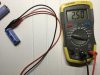
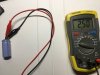
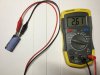
While awaiting for my parts, I ordered a cheap capacitor meter and measured those 4 2200uf/35v capacitors, readings are below, does this mean they are still all good? Even the one with really bad surface corrosion?
FB3CC105-8A84-4811-97AD-76E6C81F7D70.jpeg 64A5ADB8-617F-4E53-9A9F-0B3511EC5E8F.jpeg 0587DA38-48AD-45D6-89C5-52F15EC750B3.jpeg 3CC306C1-22D8-4747-A3EF-9B282DCE555F.jpeg
 
Back
Top Bottom