Did not realize the transistor tester I got can test capacitor as well. So these are the readings, are they still within spec? And still good? Just curious.


You are using an out of date browser. It may not display this or other websites correctly.
You should upgrade or use an alternative browser.
You should upgrade or use an alternative browser.
Questions on newly acquired NAD 7020
- Thread starter EC1
- Start date


Finally received parts, put everything back together, DBT seems ok. Plug it in, no smoke. Seems good.
Check DC, left channel is good on about 5 mv. Right channel is different story, it jumps all over the place and sometimes it goes as high as 0.9v. Turn the trimmer seems not doing that much. Finally settled at about 310 mv, no good. I thought was the trimmer. As I recalled, when I first got the unit, the right side DC was bad at around 800 mv but I was luckily able to adjust it back and trimmer feels iffy already.
Turn the unit upside down measure the trimmer resistance with different position setting and it seems ok. DMM was set to 20k ohm, and it reads 1.61 (k ohm?) all the way clockwise and 0.01 all the way counterclockwise. The left channel trimmer measured at about 0.93.
Did hook it up to a pair of test speakers, sounds good as before but don’t want to risk other speakers, so where do I go from now? Is there a “differential” pair transistors I should look into?
Check DC, left channel is good on about 5 mv. Right channel is different story, it jumps all over the place and sometimes it goes as high as 0.9v. Turn the trimmer seems not doing that much. Finally settled at about 310 mv, no good. I thought was the trimmer. As I recalled, when I first got the unit, the right side DC was bad at around 800 mv but I was luckily able to adjust it back and trimmer feels iffy already.
Turn the unit upside down measure the trimmer resistance with different position setting and it seems ok. DMM was set to 20k ohm, and it reads 1.61 (k ohm?) all the way clockwise and 0.01 all the way counterclockwise. The left channel trimmer measured at about 0.93.
Did hook it up to a pair of test speakers, sounds good as before but don’t want to risk other speakers, so where do I go from now? Is there a “differential” pair transistors I should look into?
Attachments
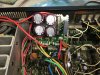
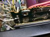
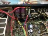
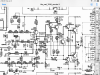
@jhjove, if you can see my post #7. No, I can’t even locate these parts, so badly mark and no pcb marking in SM.
Thinking may be the differential transistors if there are ones in this circuit. I was comparing this to one of the nad 3020 power amp circuit, they are almost identical to me. Could they be Q603/605?
@leesonic, no this is the original 20 k (it says 20kb, not sure what “b” means). I measured it off the board, the readings on the pins are 18.4K to 0 at one and 0 to 18.4 k at the other pin. So I guessing it is working alright.Are these new trimmers or the old ones?
Did you recap the amp or just the 4 psu caps? If just the 4 caps you should really think about doing it all.
With those old skeleton trimmers you need to remember that these haven't been touched for 30+years and the carbon track will now be contaminated, when your adjusting these measured voltage will bounce around a lot, my advice replace with good quality multiturns like vishay or bourns. You will have to extend the center leg to make them fit, easiest to do this when the two outside legs are soldered in place.
With those old skeleton trimmers you need to remember that these haven't been touched for 30+years and the carbon track will now be contaminated, when your adjusting these measured voltage will bounce around a lot, my advice replace with good quality multiturns like vishay or bourns. You will have to extend the center leg to make them fit, easiest to do this when the two outside legs are soldered in place.
With the bias current adjustment your post 7 is nearly there.
The solder blobs are where you would but the 1k resistors, so they are in parallel with r648/647
Let the amp warm up for 10mins
Measure voltage across r660 and r659 is the voltage between 30-60mv great, take the 1k resistors out and your done, if not between 30-60mv then you have to adjust the voltage of the rx resistors, as you have mentioned the easiest way to do this is replace what's there with 1k trimmers, to install solder the center pin to either outside pins then install. Adjust till your between the correct voltages ( although I would recommend 30mv) monitor it over the next 30 minutes adjusting if you need to. When finished remove the 1k resistors.
If there are any solder shorts from the factory these need to be put back.
The solder blobs are where you would but the 1k resistors, so they are in parallel with r648/647
Let the amp warm up for 10mins
Measure voltage across r660 and r659 is the voltage between 30-60mv great, take the 1k resistors out and your done, if not between 30-60mv then you have to adjust the voltage of the rx resistors, as you have mentioned the easiest way to do this is replace what's there with 1k trimmers, to install solder the center pin to either outside pins then install. Adjust till your between the correct voltages ( although I would recommend 30mv) monitor it over the next 30 minutes adjusting if you need to. When finished remove the 1k resistors.
If there are any solder shorts from the factory these need to be put back.
@reddish75, no, I just replaced those 4 PSU capacitors only at this moment. I was hoping to bring it up to some baseline then start the whole recap.
I understand the DC up and down, might be the old trimmer but it does not bring the DC down to the spec, the issues seem be somewhere else? That is why I am thinking the differential transistors. Does this circuit have ones, are they Q603/Q605, can someone confirm that?
Thanks for confirming the bias adjustment, have to read and understand it before I go in.
I understand the DC up and down, might be the old trimmer but it does not bring the DC down to the spec, the issues seem be somewhere else? That is why I am thinking the differential transistors. Does this circuit have ones, are they Q603/Q605, can someone confirm that?
Thanks for confirming the bias adjustment, have to read and understand it before I go in.

jhjove
Well-Known Member
@jhjove, if you can see my post #7. No, I can’t even locate these parts, so badly mark and no pcb marking in SM.
Thinking may be the differential transistors if there are ones in this circuit. I was comparing this to one of the nad 3020 power amp circuit, they are almost identical to me. Could they be Q603/605?
Yes, I did read that post and the instructions in the SM. Probably will have to trace these connections and components.
In the feedback loop, the only "diff" pair(s) to match I see are the Q603/Q605 (Q604/Q606) BC556 PNPs as well.
@reddish75, no, I just replaced those 4 PSU capacitors only at this moment. I was hoping to bring it up to some baseline then start the whole recap.
I understand the DC up and down, might be the old trimmer but it does not bring the DC down to the spec, the issues seem be somewhere else? That is why I am thinking the differential transistors. Does this circuit have ones, are they Q603/Q605, can someone confirm that?
Thanks for confirming the bias adjustment, have to read and understand it before I go in.
It's more than likely a duff cap or dry joint in this series of Nad as I've said, these are well known problem areas, sort these before potentially looking for something else.
Trimmers 0.5 watt
@reddish75, you said "The solder blobs are where you would but the 1k resistors, so they are in parallel with r648/647"
I thought I need to add the 1K resistors onto R647/R648 to be parallel but actually I can solder the 1K to the solder blobs? Just want to make sure. so I can solder the 1K resistor to the backside (trace side) of the solder blobs then use alligator clip to the resistor leg and measure it, correct? just need to be careful not to short anything. Thanks again.
I thought I need to add the 1K resistors onto R647/R648 to be parallel but actually I can solder the 1K to the solder blobs? Just want to make sure. so I can solder the 1K resistor to the backside (trace side) of the solder blobs then use alligator clip to the resistor leg and measure it, correct? just need to be careful not to short anything. Thanks again.
Do you have a multimeter? Put it on continuity mode and check that resistors r647 and 648 show continuity with the solder blobs on the corresponding side, if they do take the blobs off with desoldering braid clean up with isopropyl alcohol and a qtip top and bottom of board, then solder 1k resistors in, yes to the trace side if needed but not pressed up on to the board. no need for a clip.
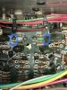
@reddish75, @jhjove, thanks for your help, parts ordered, will see.