• The move to the new server is done. There are some software and database maintenance updates in process. This has us passing the hat around to help out. We appreciate any donations. Seriously, even a dollar helps. The payment page may be found here - https://www.audiokarma.org/support.html

Questions on newly acquired NAD 7020

So I pulled out Q604 and Q606 today and found them to be “A733, P299” instead of BC556A listed.
And Q604 measured hfe 253, Vbe 698; Q606 measured hfe 268, Vbe 702. These numbers seem pretty “matched” to me?
I just ordered some BCA556A, do I need to order something different now since these 2 are now A733? (Even by looking at the readings, not sure these are my high DC offset cause now?) my hope of resolving the issue by replacing the transistors is diminishing now.
 
If you have not already done this: remove the "pre-amp out" to "normal-in" jumpers and re-check the DC offset to be certain the power amp is the culprit.
This isolates the power amp...signal-wise.
 
I thought I did but can’t remember now. I will probably wait till the new BC556A arrive then see which pair to put back on then do the test again since I want to minimize the times touching those traces.
BTW, I read some where that KSA 992 could be the replacement for A733? Any idea?
 
Can’t wait till BC556A to arrive, get a matching pair of KSA992, hfe: 392/394, Vbe: 643/645 comparing to the stock A733 of hfe: 253/268, Vbe: 698/702. DBT ok, check DC offset at right. Same thing, settles down at around 250 after 15, 20 mins, comparing to 450 earlier. Don’t know what to check now?
Also touching up 2 questionable solder joints at the power regulator circuit.
@jhjove, did pull the jumpers, the problem stays so it seems reside in power amp board.
 
Another question, can someone educate me.
At the emitter and collector of the Q609, or Q610, (red circle) are they supposed to have the same voltage? Just one is positive and one is negative?
BE570D16-F6C4-40D7-A206-BF8B8D27C8E7.jpeg
 
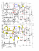
After days and weeks of poking around, hopeless, it just did not go nowhere, the readings below are what I collected and with my level, can’t not guarantee there are no miss reading, miss label but I am hoping someone with experienced eyes can shed some light on my high dc offset issue here. The yellow highlighted components are either pulled out, tested ok, or replaced or swapped between left and right channel, just try to narrow down the cause as much as I can do. And so far, with all things I did, they have improved anything yet.
2D2FE6ED-0D5E-4193-A6FA-605B03BD1FBF.png
 
OK, soooooo..... I just read through this thread, and realized something hilarious... i know you must have sold this NAD 7020... because I have it now ;p
I thought those new caps you in the pics on this thread looked like the caps that were on the one I acquired... and sure enough... same serial numbers!

I may as well give an update to this story... I brought home the NAD knowing it needed work, and it actually worked great right away, even though one channel was supposed to be out. It worked great for a few days in the garage, while I was recapping a NAD 2150, until.... zzzzaaaaappppp. It was just sitting there playing and a strong electrical buzz just started emanating from the speakers. I jumped over and shut it off and knew my luck on this one was gonna run out at some point.

In any case, I'm in the same spot you were in. What i assume is a strong DC current (I think) measures at the right speaker terminals. Like you, I suspected the Trimmers and fiddles with those to no avail. I even had some Bournes in my shopping cart to buy right before I found this thread. I don't FEEL like that's the right solve for this issue, but figured it was worth a shot. Looking at all the troubleshooting you already went through, I think we need a REAL professional ;). cough cough... @leesonic ... Cough Cough

I'm also somewhat new at learning all of this, and when I opened up this beast and saw the jungle of wires and solder I knew I was out of my depth. I did replace the LED though! that's kinda pretty and blue now.
 
OK, soooooo..... I just read through this thread, and realized something hilarious... i know you must have sold this NAD 7020... because I have it now ;p I thought those new caps you in the pics on this thread looked like the caps that were on the one I acquired... and sure enough... same serial numbers! I may as well give an update to this story... I brought home the NAD knowing it needed work, and it actually worked great right away, even though one channel was supposed to be out. It worked great for a few days in the garage, while I was recapping a NAD 2150, until.... zzzzaaaaappppp. It was just sitting there playing and a strong electrical buzz just started emanating from the speakers. I jumped over and shut it off and knew my luck on this one was gonna run out at some point. In any case, I'm in the same spot you were in. What i assume is a strong DC current (I think) measures at the right speaker terminals. Like you, I suspected the Trimmers and fiddles with those to no avail. I even had some Bournes in my shopping cart to buy right before I found this thread. I don't FEEL like that's the right solve for this issue, but figured it was worth a shot. Looking at all the troubleshooting you already went through, I think we need a REAL professional ;). cough cough... @leesonic ... Cough Cough
I'm also somewhat new at learning all of this, and when I opened up this beast and saw the jungle of wires and solder I knew I was out of my depth. I did replace the LED though! that's kinda pretty and blue now.
Well, azookey, don't feel alone because it seems I have a 7020 with the same sort of problem - +19VDC at the output! I've been taking voltages, testing transistors, resistors and caps and racking my brains about this for a day or two and have yet to come up with the solution so far. I thought about posting about this problem myself but haven't given up just yet. And I was REALLY hoping, while reading EC1 & your posts, that light had been shed light upon the problem and help with the problem I'm having - as happens so often here on AK. But looks like we're shipmates at the moment!
Is it possible for two drowning people to save each other?! I'll keep at it over here for the time being and if it's safe to assume that "EC1's" problems are now your problems I'll try to keep you in the loop regarding any progress over here until and if I have to post about it. Good luck, ..shipmate!
P.S. I've worked on a lot of stereo receivers and this particular NAD model is NOT typical of vintage receivers in regard to the component placement and general difficulty in just finding stuff due to the on-board part labeling. It's atrocious! In fact this is one of the worst units I've ever seen when it comes to that so don't feel bad if you get frustrated enough to pull your hair out. Keep at it!
 
Last edited:
@azookey, sorry for dumping my issue onto you.
@mrwasabihead, I will share some of my notes if those can be any help, assuming I still can find them, as you can see this post here most of time is just me documenting my progress barely getting that much of attention. And as you mentioned, one of the difficulties for me is flipping the unit back and forth to find the part location and the corresponding soldering pins.
 
Sounds good all around. I don’t mind having an ongoing project… maybe it’s easier for me to say because I have a good amount of other NAD gear I use

I went ahead and put in the order for those trimmers along with some other stuff for a different unit I want to recap. I’ll keep the thread updated.
 
Reading through this again, @EC1, @azookey; the BC556A replacement for the 2sa733....check the pinout diagrams. This what I found:
BC556A - CBE
2SA733 - ECB
 
I've never seen these early NAD amps and receivers run anything other than BC series transistors. No sense in replacing these with KSA/KSC series. If your receiver has anything but BC series (apart from where indicated in the schematic), then someone has been in there before. I would be inclined to pull all the non-standard transistors and install BC ones. Test the output and other medium power transistors, or you could even replace the BC139/140s if you so desire.

As others have suggested, pull the pre and power jumper to separate the two. There is no harm in pulling resistors to measure them. Caps too if you have one of those fancy but inexpensive MK168 testers that test any component. Look for solder bridges or dry joint on the board. I feel your pain though.

I've never seen any NAD receiver that doesn't have silk screening on the PCB showing where all the components are. No better or worse than other pieces of that era, and certainly not "atrocious". Sometimes, it makes things easier to print out the PCB layout from the service manual, and if you have to, reverse the image so it reflects (no pun intended) what you're actually looking at.
 
I was thinking about putting the new BC transistors back in but somehow the other channel works with the KSA and that is why just left them as they are. As I recall, the KSA hfe is higher than BCs. And the KSC is even higher.
I almost pull out every resistors and caps on the bad channel and they all tested ok other than some lower value caps which are like 40 % off and those 22p which my tester does not go down that low. I need to find my notes to see what they are though.
I spend a lot of effort on this unit trying to get it fixed but somehow with my limited knowledge and experience, it just seems not worth anymore. And now @azookey has it.
 
I've never seen any NAD receiver that doesn't have silk screening on the PCB showing where all the components are. No better or worse than other pieces of that era, and certainly not "atrocious". Sometimes, it makes things easier to print out the PCB layout from the service manual, and if you have to, reverse the image so it reflects (no pun intended) what you're actually looking at.
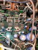
@leesonic From the picture below you can see that a good number of resistors have ceramic stand-offs on the leads and most of the printing of the resistor numbers is done over the actual circuit board hole so when the resistor is inserted the stand-offs and/or leads obscure a good deal of the numbers. It's a crazy tight fit all the way around in the output section, and as EC1 said, a good deal of time is spent just finding things. This not even considering the copious amount of glue pumped in under caps and over to tops of diodes, resistors and jumpers. Though a pain to be found on a number of vintage manufacturers units, on this one, it all adds up to a serious PITA! Also, there's no board component layout offered in the service manual, ...that I have at least. I truly wish there was. : )
It could have and should have been done better. But hey, that's the 80's for you.
 

Attachments

  • 1.jpg
    1.jpg
    159.7 KB · Views: 10
@mrwasabihead, as I recall, there is a diode hidden, buried deep there, mine was corroded with the glue, you might want to check that out. I was so happy to discover that at that time thinking this was the cause of my issue but it still turned out not.
F18BB565-F777-4F29-9799-83CBB97CC6FF.jpeg
 
@mrwasabihead, as I recall, there is a diode hidden, buried deep there, mine was corroded with the glue, you might want to check that out. I was so happy to discover that at that time thinking this was the cause of my issue but it still turned out not.View attachment 2518613
Yeah, I've got that going on too. Jumpers corroded, diodes and resistors buried etc. One of the first things I did was check the all the diodes and transistors. I've actually got one channel (L) that will just need to be adjusted in the end, it's currently at about 35mV. The right, as I mentioned, is at +19VDC. I'm pretty busy around here these days and I may have to "phone a friend" that can probably help with what's going on here. But whether I get it sorted out here on AK or here in the shop I'll keep up on this thread.
 
Last edited:
Back
Top Bottom