You are using an out of date browser. It may not display this or other websites correctly.
You should upgrade or use an alternative browser.
You should upgrade or use an alternative browser.
Rare Beauty: Fairchild's 275 Amplifier
- Thread starter dcgillespie
- Start date

AGREED!
- Woody
Funny boy.

CIRCUIT ANALYSIS
Boy oh boy -- lots of observations being made and data being gathered, and a few problems uncovered as well. I hope I can present it all in a cohesive manner:
1. Published Schematics: The first circuit I can find was published in a Radio & Television News article dated Nov, 1956. Unless a schematic of earlier dating comes along, I am considering this the original schematic of the amplifier. In Jan 1957, Fairchild published an updated schematic. It has mistakes on it, and includes general updates such as specifying GZ34 rectifier tubes and lowering output tube quiescent current, but the real take away is the unveiling of a completely revised NFB system and approach to tailoring the HF response of the amplifier. Sams came out with their folder on the amplifier in Dec of 57, which has its own errors, but makes the usual Sams effort of depicting both designs.
2. Published Performance Specifications (of notable relevance):
As provided with their original sales literature:
A. Power Output: 65 watts at less than 0.5 IMD.
B. Frequency Response: +0/-0.5 db 20 Hz to 20 kHz at any level up to 70 watts.
C. Sensitivity: Less than 0.7 volts rms for rated output.
D. Hum and Noise: Greater than 90 db below rated output (<1 mv on 16Ω tap).
As provided in their Model 275 Instruction Manual (which also includes the updated schematic):
A. Power Output: 70 watts at less than 2% IMD.
B. Frequency Response: +0/-0.5 db 20 Hz to 20 kHz at any level up to 65 watts.
C. Sensitivity: Less than 0.5 volts rms for rated output.
D. Hum and Noise: 85 db below rated output.
Two observations from this data -- one minor, one major: (1) It looks like the power output wars reached even the Fairchild Corporation as well: Power Output was increased in part by allowing a wider distortion tolerance, and (2) Based on my work with a number of other amplifiers that were in production during this time frame, it is highly likely that the original design was found to have HF stability issues relative to the quickly changing standard for stability that was taking place at that time (the original design had a number of elements that were acting to boost HF response, while the updated design has none of those, and elements installed to actually reduce it). Note again the relaxed distortion standard and importantly, the greater sensitivity associated with the updated circuit. This all speaks to a reduced NFB level (which the revised design has), as part of an overall effort to enhance (at least) HF stability.
The amplifiers here include (by in large) the updated NFB, HF stability, and Damping Controls circuits (other than the missing components in the damping circuit), and the effect of the changes is notable. Fairchild's published specifications (any of them) are rather general in nature, specifying no THD performance, and frequency response only up to 20 kHz. The amplifier here meets the published frequency response performance, but with no information for response above that range, the only indication that can be had for proper performance in that region comes through a comparison made between the square wave presentation as shown in the Radio and Television article (surely made by the original design since that is what's presented in that article), and that produced by the amplifier here. And differences certainly exist, which are supported by the changes made to the updated version:
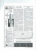
Note the square wave presentation at the bottom right of this page. From the description, it is a 6 kHz presentation made at 40 watts output, with the variable damping "at a minimum" (I believe what is meant here is with the control set for maximum damping -- i.e., the damping circuit turned off). The impedance tap being used is not stated, but it was quite customary in the day to perform all testing at the 16Ω tap:
Now, take a look at the scope shot here of a 6 kHz square wave made at 40 watts output, with the Damping Control turned off, as taken at the 16Ω tap:
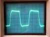
The primary differences to note are the article's image shows a very flat and parallel top/bottom of the waveform, with tight corners. I have little doubt that most feedback amplifier designs with this display at this frequency in fact have HF stability issues. Now look at the square waves produced from the amplifier here. The tops and bottoms are not parallel (indicating notable phase shift), and the corners are well rounded, indicating a limited HF response.
When a more traditional 10 kHz square wave is used, the defects are exaggerated even further (the higher amplitude was just me being lazy and not equalizing the amplitude in both presentations):

Understand that a square wave is a fundamental frequency, with an infinite number of odd harmonics added to it. Therefore, it is generally understood that for a circuit to pass a square wave with reasonable fidelity, the circuit must be able to pass a band of frequencies that is equal to the fundamental frequency F/10 on the low end, to F X 10 on the high end, and do so with equal amplification and phase shift properties at all frequencies throughout that band pass.
The measured frequency response of the amplifier here (@1 watt @ 16Ω) is:
@1 kHz = 0.0 db (ref)
@ 10 kHz = +0.7 db
@ 20 kHz = -0.4 db
@ 30 kHz = -2.5 db
@ 40 kHz = -4.7 db
@ 50 kHz = -6.8 db
@ 60 kHz = -8.5 db
So the supersonic response drops off a cliff pretty quickly, which is exactly why the square wave shown is being produced. The kick at 10 kHz is likely being produced by the damping circuit components that remain in play even when that circuit is turned off. I have suggested to my client that the Variable Damping circuit should be eliminated, as it long ago became an anachronism, almost a fad that disappeared about as quickly as it appeared. Removing the circuit properly however would entail developing a new NFB and HF stability scheme, which can certainly be done -- but then that starts to beg other questions.
I've often stated that from my perspective, it is the circuit that creates the sound we hear -- not the character of the individual components. I know that cuts sideways with a lot of folks, and I appreciate that all opinions are valid. But my perspective is one that has been proven out many times over the years. Now not wanting to start that debate here, where I'm going with this is that if you modify the circuit for provably better measured performance, what if that cuts against the sound that folks have come to know these amplifiers by? That is, it may very well be that it is because of the limited response and phase characteristics shown that folks enjoy the sound as much as they do.
I have long observed that more than just a few people would (often enough) rather listen to their little Maggy amplifier, than (no disrespect meant at all), a classic Mac amplifier that is darn near all but perfect in terms of measured performance (I have a C11 and MC240). Why is this? The Mac is extremely faithful to the original definition of High Fidelity, while the Maggy is (by comparison) limited in just about every way possible you can think of. I have concluded that it is the looser damping, more rolled off presentation of the Maggy that takes the edge off just enough, and loosens up the low end just enough, to make for a very enjoyable listening experience, even though it is certainly less accurate.
Now I'm hardly trying to imply that the 275 is akin to a Magnavox. Quite the contrary. However, it does have what effectively amounts to signal shaping circuits in the dual feedback paths (unique to the updated design) that can affect the reproduced sound. There are a whole bunch more tests to be made to determine the characteristics of these networks. So taking things a step at a time, I always try to consider all sides before taking that next step. A new network may produce a wow or nope, I like the way it was. But at least knowing the reality of what is allows the questions to be pondered before the next step is taken or decided. Comments always welcomed.
Now the Hum and Noise performance is an issue for another time, and needs addressing as well.
Dave
Boy oh boy -- lots of observations being made and data being gathered, and a few problems uncovered as well. I hope I can present it all in a cohesive manner:
1. Published Schematics: The first circuit I can find was published in a Radio & Television News article dated Nov, 1956. Unless a schematic of earlier dating comes along, I am considering this the original schematic of the amplifier. In Jan 1957, Fairchild published an updated schematic. It has mistakes on it, and includes general updates such as specifying GZ34 rectifier tubes and lowering output tube quiescent current, but the real take away is the unveiling of a completely revised NFB system and approach to tailoring the HF response of the amplifier. Sams came out with their folder on the amplifier in Dec of 57, which has its own errors, but makes the usual Sams effort of depicting both designs.
2. Published Performance Specifications (of notable relevance):
As provided with their original sales literature:
A. Power Output: 65 watts at less than 0.5 IMD.
B. Frequency Response: +0/-0.5 db 20 Hz to 20 kHz at any level up to 70 watts.
C. Sensitivity: Less than 0.7 volts rms for rated output.
D. Hum and Noise: Greater than 90 db below rated output (<1 mv on 16Ω tap).
As provided in their Model 275 Instruction Manual (which also includes the updated schematic):
A. Power Output: 70 watts at less than 2% IMD.
B. Frequency Response: +0/-0.5 db 20 Hz to 20 kHz at any level up to 65 watts.
C. Sensitivity: Less than 0.5 volts rms for rated output.
D. Hum and Noise: 85 db below rated output.
Two observations from this data -- one minor, one major: (1) It looks like the power output wars reached even the Fairchild Corporation as well: Power Output was increased in part by allowing a wider distortion tolerance, and (2) Based on my work with a number of other amplifiers that were in production during this time frame, it is highly likely that the original design was found to have HF stability issues relative to the quickly changing standard for stability that was taking place at that time (the original design had a number of elements that were acting to boost HF response, while the updated design has none of those, and elements installed to actually reduce it). Note again the relaxed distortion standard and importantly, the greater sensitivity associated with the updated circuit. This all speaks to a reduced NFB level (which the revised design has), as part of an overall effort to enhance (at least) HF stability.
The amplifiers here include (by in large) the updated NFB, HF stability, and Damping Controls circuits (other than the missing components in the damping circuit), and the effect of the changes is notable. Fairchild's published specifications (any of them) are rather general in nature, specifying no THD performance, and frequency response only up to 20 kHz. The amplifier here meets the published frequency response performance, but with no information for response above that range, the only indication that can be had for proper performance in that region comes through a comparison made between the square wave presentation as shown in the Radio and Television article (surely made by the original design since that is what's presented in that article), and that produced by the amplifier here. And differences certainly exist, which are supported by the changes made to the updated version:
Note the square wave presentation at the bottom right of this page. From the description, it is a 6 kHz presentation made at 40 watts output, with the variable damping "at a minimum" (I believe what is meant here is with the control set for maximum damping -- i.e., the damping circuit turned off). The impedance tap being used is not stated, but it was quite customary in the day to perform all testing at the 16Ω tap:
Now, take a look at the scope shot here of a 6 kHz square wave made at 40 watts output, with the Damping Control turned off, as taken at the 16Ω tap:
The primary differences to note are the article's image shows a very flat and parallel top/bottom of the waveform, with tight corners. I have little doubt that most feedback amplifier designs with this display at this frequency in fact have HF stability issues. Now look at the square waves produced from the amplifier here. The tops and bottoms are not parallel (indicating notable phase shift), and the corners are well rounded, indicating a limited HF response.
When a more traditional 10 kHz square wave is used, the defects are exaggerated even further (the higher amplitude was just me being lazy and not equalizing the amplitude in both presentations):
Understand that a square wave is a fundamental frequency, with an infinite number of odd harmonics added to it. Therefore, it is generally understood that for a circuit to pass a square wave with reasonable fidelity, the circuit must be able to pass a band of frequencies that is equal to the fundamental frequency F/10 on the low end, to F X 10 on the high end, and do so with equal amplification and phase shift properties at all frequencies throughout that band pass.
The measured frequency response of the amplifier here (@1 watt @ 16Ω) is:
@1 kHz = 0.0 db (ref)
@ 10 kHz = +0.7 db
@ 20 kHz = -0.4 db
@ 30 kHz = -2.5 db
@ 40 kHz = -4.7 db
@ 50 kHz = -6.8 db
@ 60 kHz = -8.5 db
So the supersonic response drops off a cliff pretty quickly, which is exactly why the square wave shown is being produced. The kick at 10 kHz is likely being produced by the damping circuit components that remain in play even when that circuit is turned off. I have suggested to my client that the Variable Damping circuit should be eliminated, as it long ago became an anachronism, almost a fad that disappeared about as quickly as it appeared. Removing the circuit properly however would entail developing a new NFB and HF stability scheme, which can certainly be done -- but then that starts to beg other questions.
I've often stated that from my perspective, it is the circuit that creates the sound we hear -- not the character of the individual components. I know that cuts sideways with a lot of folks, and I appreciate that all opinions are valid. But my perspective is one that has been proven out many times over the years. Now not wanting to start that debate here, where I'm going with this is that if you modify the circuit for provably better measured performance, what if that cuts against the sound that folks have come to know these amplifiers by? That is, it may very well be that it is because of the limited response and phase characteristics shown that folks enjoy the sound as much as they do.
I have long observed that more than just a few people would (often enough) rather listen to their little Maggy amplifier, than (no disrespect meant at all), a classic Mac amplifier that is darn near all but perfect in terms of measured performance (I have a C11 and MC240). Why is this? The Mac is extremely faithful to the original definition of High Fidelity, while the Maggy is (by comparison) limited in just about every way possible you can think of. I have concluded that it is the looser damping, more rolled off presentation of the Maggy that takes the edge off just enough, and loosens up the low end just enough, to make for a very enjoyable listening experience, even though it is certainly less accurate.
Now I'm hardly trying to imply that the 275 is akin to a Magnavox. Quite the contrary. However, it does have what effectively amounts to signal shaping circuits in the dual feedback paths (unique to the updated design) that can affect the reproduced sound. There are a whole bunch more tests to be made to determine the characteristics of these networks. So taking things a step at a time, I always try to consider all sides before taking that next step. A new network may produce a wow or nope, I like the way it was. But at least knowing the reality of what is allows the questions to be pondered before the next step is taken or decided. Comments always welcomed.
Now the Hum and Noise performance is an issue for another time, and needs addressing as well.
Dave

I was struck by this phenomena as well, not with a Fairchild, but with a DIY sweep tube amp I recently finished. The amp measures poorly in the metric of THD (and probalby IMD too), as well as full power frequency response, but it is absolutely one of the sweetest sounding amps I have and is really enjoyable to listen to.However, it does have what effectively amounts to signal shaping circuits in the dual feedback paths (unique to the updated design) that can affect the reproduced sound.
0.5V to 0.7V input sensivity? Geesh that's a sensitive power amp for such large power capacity. I used to think I liked sensitive amps because it afforded me the option to drive them directly from my frontend electronics, bypassing the preamp. But lately I've started to use my preamp more, and I really like what a well designed and executed preamp does for being able to drive the power amp with authority. Even if my amps are somewhat sensitive, these days I still prefer driving them with my preamp because I think it just sounds better.Now the Hum and Noise performance is an issue for another time
Anyway, looking forward to seeing your proposed changes to improve these units!
Last edited:
K -- Agreed. Back in the day, there was really no standard for sensitivity. On the one end, you had the Williamson design that could take upwards of 2.0 volts rms input signal to produce all of about 8-10 watts of power output, or on the other end, the Mullard designs that could produce at least double that power at a minimum, but requiring only a fraction of a volt input signal (100 -200 mv) to produce it. As a result, there were preamp designs with various levels of gain built into them (I've seen designs with line stage gains of 0 to about X15), and the more sensitive power amps always had input level controls provided to help match them to the gain of the preamp they were being used with. It was the ultimate audio mix and match game, with everybody trying to produce equipment that would work with everybody else's. In my opinion, the best performance comes from having matched shoes and shoe laces, so that a level control is not needed -- or -- at least employ a power amp design whose performance is not affected by the setting of its level control -- which is what Fairchild did with the 275.
The whole idea of having a separate preamp and power amp is to minimize hum and noise, period. There's really no other reason to separate the two circuits except for maybe some custom installation requirement. And, the greater the power output involved, the greater the need to separate the two circuits in a close listening environment. But relative to the advantage this separation creates, the advantage can be destroyed really quickly by trying to make the power amp too accommodating sensitivity wise. There are a lot of factors that come into play -- such as speaker sensitivity, source level, listening level, and volume control position relative to range of loudness tap operation, etc. -- but I've generally found that sensitivity levels requiring at least a volt for lower powered amplifiers, and 2 volts or more for higher powered amplifiers tends to produce the best S/N ratio in a residential application.
Judged in that light then, the updated 275 is in fact quite sensitive for the power output it produces. The example here produced 60 watts RMS with a mere 0.44 vac rms applied to the input (meeting Fairchild's specification of less that 0.5 vac for the updated design). None the less, while high power amp sensitivity always aggravates the issue of hum and noise, with careful execution of build, even designs with sensitivity/power output levels on the order that the 275 displays can still be tamed to produce S/N ratios of 90 db or better. In this case however, I think there's more going on than just high sensitivity levels, but more investigation needs to be done before diving into that issue.
Dave
The whole idea of having a separate preamp and power amp is to minimize hum and noise, period. There's really no other reason to separate the two circuits except for maybe some custom installation requirement. And, the greater the power output involved, the greater the need to separate the two circuits in a close listening environment. But relative to the advantage this separation creates, the advantage can be destroyed really quickly by trying to make the power amp too accommodating sensitivity wise. There are a lot of factors that come into play -- such as speaker sensitivity, source level, listening level, and volume control position relative to range of loudness tap operation, etc. -- but I've generally found that sensitivity levels requiring at least a volt for lower powered amplifiers, and 2 volts or more for higher powered amplifiers tends to produce the best S/N ratio in a residential application.
Judged in that light then, the updated 275 is in fact quite sensitive for the power output it produces. The example here produced 60 watts RMS with a mere 0.44 vac rms applied to the input (meeting Fairchild's specification of less that 0.5 vac for the updated design). None the less, while high power amp sensitivity always aggravates the issue of hum and noise, with careful execution of build, even designs with sensitivity/power output levels on the order that the 275 displays can still be tamed to produce S/N ratios of 90 db or better. In this case however, I think there's more going on than just high sensitivity levels, but more investigation needs to be done before diving into that issue.
Dave

Yes, not working on my end either.Is it me or is anyone else getting an error message when clicking on the pics to enlarge them?

ON -- The pictures originally posted haven't enlarged for anybody -- including me! I re-posted them all again in post #14, which work fine, as have all pics since......
Dave
Dave

My Rauland-Borg amps in stock form hit max output at somewhere just under 0.2v input. I made some changes and its now closer to 0.6v, which is honestly still too sensitive. Been meaning to go back in there and knock the gain back some more on the first stage. Its easy on that one at least, the first gain stage is outside the feedback loop.
CIRCUIT ANALYSIS - CON'T
A bunch more information to add now for consideration:
1. Output Transformer: Measurements produced the following results:
Primary impedance:
4Ω on 4Ω tap = 3564Ω.
8Ω on 8Ω tap = 3530Ω.
16Ω on 16Ω tap = 3490Ω
This relates closely to the 3400Ω figure given by Todd in their Radio and Television News article.
Screen Taps are located at 24.95% of the primary winding.
The amplifier/transformer met the power response specification, being down 0 db from 60 watts at 20 Hz (ref: 1 kHz), and down slightly less than 1 db at 20 kHz.
The screen tap position is quite curious to operate 6550s at, and does not qualify as "UltraLinear" operation of the tubes as the R&T article states. UltraLinear operation of 6550 tubes occurs with screen taps placed at 40% on a 4000Ω plate load. The slightly lower reflected plate load of the 275's transformer would place the optimum screen tap for that load a few percentage points lower than 40%, but nowhere near the (basically) 25% location offered by the transformer. As a result, this transformer may in fact be more suitable for operation with EL34 tubes, but those tests will come later.
Besides the excellent power response, another excellent feature of this transformer's design is that other than for amplitude, a 10 kHz square wave presentation is identical at each impedance tap. This is not always the case with transformers from the mid 50s, which can complicate stabilization issues, or limit stability when NFB is applied. With this transformer however, the very consistent response/phase characteristic at each output tap makes for identical HF stability at each output tap, with the design in fact producing absolutely HF stability into any type of load. Testing for LF stability has yet to be done, but no obvious signs of antisocial behavior have been observed as yet.
2. Negative Feedback:
The updated amplifier changed from a rather traditional (i.e., effectively full response) single negative voltage feedback loop in the original design, to a new bi-loop (single source with two tracks) design, with both tracks of the loop having frequency sensitive circuit elements within it -- much more than just a typical phase advance cap across the FB resistor to control supersonic response. With the dual HF step networks removed (so as to clearly show the effects of just the feedback networks), both tracks together provide a total of 15 db of negative voltage feedback at 1 kHz, with the amount of feedback in each track changing significantly with frequency:
A. @ 1 kHz: 47K track = 12.7 db NFB (ref). 15K track = 2.3 db NFB.
B. @ 100 Hz: 47K track = 14.1 db NFB (ref). 15K track = 0.1 db NFB.
C. @ 10 kHz: 47K track = 4.9 db NFB (ref). 15K track = 8.8 db NFB.
Total NFB is reduced somewhat on either side of 1 kHz as can be seen, but the biggest change occurs between the two tracks with changing frequency.
Why Fairchild made such a rather radical change in the feedback system can only be speculated on, but it almost surely had to do with some aspect of amplifier stability -- and remember, it may not have been the stability produced with the damping at maximum (turned off), but when the negative current feedback network is engaged to reduce amplifier damping. From my own experience, I know that for such systems to provide enough effective range, they can then introduce their own element of instability, so the change may be for reasons associated with issues in that circuit. The only way that could be determined for certain however would be to build the original FB/HF stability circuits into the amplifier and test them, but that takes the project off on a tangent of no particular value to my client, so I have no plans to pursue that.
My suspicions are that based on the design changes made, the anticipation was that the amplifier would regularly be operated at some level of reduced damping. In fact, a quick check of the instruction manual has just borne that out, where I find it recommends operation with the control set midway if it otherwise produces no obvious (or worthwhile) change in the bass response of the connected speaker system at any other setting. Therefore, barring anything else to indicate otherwise, the change would now seem to be all but confirmed as made to enhance damping control performance. But with the whole variable damping thing being an anachronism today, it makes for a strong case then to investigate a new loop that would optimize the amplifier when maximum damping is the goal. So, I plan to go ahead and look into that next. In the mean time.........
3. Signal to Noise Ratio: The amplifier was failing terribly in this department, producing a ratio of only 65 db below 60 watts. One of the largest contributors to the noise was found to be this:
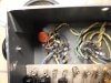
This is the 6AB4 input stage. The yellow and green leads is the heater wiring, which as can be seen is pushed right up under the plate load resistor, and next to the first step network of the design, making for a huge transfer of 60 Hz noise into the signal path to be amplified by all succeeding stages. Repositioning that wiring away from those components went a long way in quieting this sucker down.
I have included copies of the schematics I have (such as they are) for those who wish to refer to them.
Early Version:
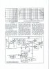
Later Version:

More as it becomes available.
Dave
A bunch more information to add now for consideration:
1. Output Transformer: Measurements produced the following results:
Primary impedance:
4Ω on 4Ω tap = 3564Ω.
8Ω on 8Ω tap = 3530Ω.
16Ω on 16Ω tap = 3490Ω
This relates closely to the 3400Ω figure given by Todd in their Radio and Television News article.
Screen Taps are located at 24.95% of the primary winding.
The amplifier/transformer met the power response specification, being down 0 db from 60 watts at 20 Hz (ref: 1 kHz), and down slightly less than 1 db at 20 kHz.
The screen tap position is quite curious to operate 6550s at, and does not qualify as "UltraLinear" operation of the tubes as the R&T article states. UltraLinear operation of 6550 tubes occurs with screen taps placed at 40% on a 4000Ω plate load. The slightly lower reflected plate load of the 275's transformer would place the optimum screen tap for that load a few percentage points lower than 40%, but nowhere near the (basically) 25% location offered by the transformer. As a result, this transformer may in fact be more suitable for operation with EL34 tubes, but those tests will come later.
Besides the excellent power response, another excellent feature of this transformer's design is that other than for amplitude, a 10 kHz square wave presentation is identical at each impedance tap. This is not always the case with transformers from the mid 50s, which can complicate stabilization issues, or limit stability when NFB is applied. With this transformer however, the very consistent response/phase characteristic at each output tap makes for identical HF stability at each output tap, with the design in fact producing absolutely HF stability into any type of load. Testing for LF stability has yet to be done, but no obvious signs of antisocial behavior have been observed as yet.
2. Negative Feedback:
The updated amplifier changed from a rather traditional (i.e., effectively full response) single negative voltage feedback loop in the original design, to a new bi-loop (single source with two tracks) design, with both tracks of the loop having frequency sensitive circuit elements within it -- much more than just a typical phase advance cap across the FB resistor to control supersonic response. With the dual HF step networks removed (so as to clearly show the effects of just the feedback networks), both tracks together provide a total of 15 db of negative voltage feedback at 1 kHz, with the amount of feedback in each track changing significantly with frequency:
A. @ 1 kHz: 47K track = 12.7 db NFB (ref). 15K track = 2.3 db NFB.
B. @ 100 Hz: 47K track = 14.1 db NFB (ref). 15K track = 0.1 db NFB.
C. @ 10 kHz: 47K track = 4.9 db NFB (ref). 15K track = 8.8 db NFB.
Total NFB is reduced somewhat on either side of 1 kHz as can be seen, but the biggest change occurs between the two tracks with changing frequency.
Why Fairchild made such a rather radical change in the feedback system can only be speculated on, but it almost surely had to do with some aspect of amplifier stability -- and remember, it may not have been the stability produced with the damping at maximum (turned off), but when the negative current feedback network is engaged to reduce amplifier damping. From my own experience, I know that for such systems to provide enough effective range, they can then introduce their own element of instability, so the change may be for reasons associated with issues in that circuit. The only way that could be determined for certain however would be to build the original FB/HF stability circuits into the amplifier and test them, but that takes the project off on a tangent of no particular value to my client, so I have no plans to pursue that.
My suspicions are that based on the design changes made, the anticipation was that the amplifier would regularly be operated at some level of reduced damping. In fact, a quick check of the instruction manual has just borne that out, where I find it recommends operation with the control set midway if it otherwise produces no obvious (or worthwhile) change in the bass response of the connected speaker system at any other setting. Therefore, barring anything else to indicate otherwise, the change would now seem to be all but confirmed as made to enhance damping control performance. But with the whole variable damping thing being an anachronism today, it makes for a strong case then to investigate a new loop that would optimize the amplifier when maximum damping is the goal. So, I plan to go ahead and look into that next. In the mean time.........
3. Signal to Noise Ratio: The amplifier was failing terribly in this department, producing a ratio of only 65 db below 60 watts. One of the largest contributors to the noise was found to be this:
This is the 6AB4 input stage. The yellow and green leads is the heater wiring, which as can be seen is pushed right up under the plate load resistor, and next to the first step network of the design, making for a huge transfer of 60 Hz noise into the signal path to be amplified by all succeeding stages. Repositioning that wiring away from those components went a long way in quieting this sucker down.
I have included copies of the schematics I have (such as they are) for those who wish to refer to them.
Early Version:
Later Version:
More as it becomes available.
Dave

s-petersen
Scott
For some reason I have always liked sensitive amps, I realize they pick up more noise, but I feel they also pick up more nuanses from the music as well.
I feel that is also why I like tube vs transistors also, I feel that an electrostatic field is much more sensitive to the flow of electrons than the silicon substrate of a transistor.
These are my feelings, not necessarily facts. I am following, Interesting thread!
I feel that is also why I like tube vs transistors also, I feel that an electrostatic field is much more sensitive to the flow of electrons than the silicon substrate of a transistor.
These are my feelings, not necessarily facts. I am following, Interesting thread!
Last edited:


CIRCUIT ANALYSIS CON'T
To finish up the S/N piece, moving the heater wiring quieted things down by about 8 db, but that still left a ways to go to get to at least -85 db below rated output.
Further investigation showed that there was enough H/K leakage in the installed 6AB4, such that when it was replaced by another tube from my own stock, it reduce noise by another 9 db. I had tried a different tube in this position previously, but any gains it made were being masked by the heater wiring lead dress issue that had not been addressed at that point. With the heater wiring resolved and tube replaced, now the amplifier was was actually becoming pretty quiet (I was monitoring my progress with my meter and some sensitive phones connected directly across the 16Ω output) at - 82 db. The final improvement came from grounding the secondary B+ caps (C5A and B) at the audio ground point (front corner mounting stud of the output transformer), rather than at the power supply ground point. At this point in the circuit, these caps perform much more of a decoupling service (particularly section B) than filtering, so any ripple current through them is small. But grounded at the noisy power supply ground point (one mounting stud of the power transformer), they inject the equivalent of any noise signal that appears between the two grounding points into the audio signal at an early point in the amplification chain. By grounding these caps at the ground point for the circuits they serve, there is then no noise to inject, which can make a difference once all the other noise issues are eliminated. With this final move, the hum and noise figure for this amplifier fell to -87 db, and this is still with no bottom cover in place. Once that is installed, reaching -90 db below rated output should not be a problem. Do understand however that proper choice of a quiet 6AB4 is vital in achieving the published hum and noise performance.
Negative Feedback Loop And Stability:
Further study of the input stage shows that there was either one additional concern driving the changes made -- or at least opportunity was taken to also address an additional issue -- that being the effect of the level control setting on the HF response of the amplifier in the original design.
The original design used an 18K series resistor between the wiper of the level control, and the input grid of the first stage. Through interaction with Miller in the input stage, this becomes one of the HF tailoring networks in the design. However, with the level control itself being of such greater resistance relative to the series resistor, it means that varying the control to a midpoint setting will impact the effect Miller has on the supersonic response of the amplifier. Fairchild advertised that the control had no effect on transient or sine wave performance, but this could only have been within the audio bandwidth, as supersonic response will surely be impacted by the control setting with such a small series resistance value.
In the updated design, Fairchild increased the value of the input resistor by a factor of nearly X10 to 150K. Such a value, in conjunction with the characteristics of the 6AB4 tube (1/2 of a 12AT7), means that the effect of Miller will have already been effectively maximized by the value of the series resistor alone, meaning any further resistance added by the control will have little impact. That in turn makes amplifier response stable at any setting of the control, which is borne out on the lab bench: the control has virtually no effect on the appearance of a 10 kHz square wave presentation.
Modified Negative Feedback Loop:
In view of the compromised transient performance displayed under conditions of maximum damping, an alternate FB loop and HF stability scheme has been investigated, attempting to work as much with the original design as much as possible, but with the damping circuits completely removed from the design. The results have been extremely encouraging as shown in the 10 kHz square wave teaser presented here:
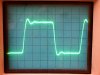
This is a near textbook display of a well designed and stabilized NFB amplifier. Performance wise, there is simply no comparison between the transient response of the stock (updated) design as shown in post #25, and that shown here from the proposed new FB loop and HF stability networks. The work is not finalized yet, but is more so than not. In the working with developing the new loop, the the output transformer of the 275 has shown its supersonic characteristics to be in a class by themselves.
More to come.
Dave
To finish up the S/N piece, moving the heater wiring quieted things down by about 8 db, but that still left a ways to go to get to at least -85 db below rated output.
Further investigation showed that there was enough H/K leakage in the installed 6AB4, such that when it was replaced by another tube from my own stock, it reduce noise by another 9 db. I had tried a different tube in this position previously, but any gains it made were being masked by the heater wiring lead dress issue that had not been addressed at that point. With the heater wiring resolved and tube replaced, now the amplifier was was actually becoming pretty quiet (I was monitoring my progress with my meter and some sensitive phones connected directly across the 16Ω output) at - 82 db. The final improvement came from grounding the secondary B+ caps (C5A and B) at the audio ground point (front corner mounting stud of the output transformer), rather than at the power supply ground point. At this point in the circuit, these caps perform much more of a decoupling service (particularly section B) than filtering, so any ripple current through them is small. But grounded at the noisy power supply ground point (one mounting stud of the power transformer), they inject the equivalent of any noise signal that appears between the two grounding points into the audio signal at an early point in the amplification chain. By grounding these caps at the ground point for the circuits they serve, there is then no noise to inject, which can make a difference once all the other noise issues are eliminated. With this final move, the hum and noise figure for this amplifier fell to -87 db, and this is still with no bottom cover in place. Once that is installed, reaching -90 db below rated output should not be a problem. Do understand however that proper choice of a quiet 6AB4 is vital in achieving the published hum and noise performance.
Negative Feedback Loop And Stability:
Further study of the input stage shows that there was either one additional concern driving the changes made -- or at least opportunity was taken to also address an additional issue -- that being the effect of the level control setting on the HF response of the amplifier in the original design.
The original design used an 18K series resistor between the wiper of the level control, and the input grid of the first stage. Through interaction with Miller in the input stage, this becomes one of the HF tailoring networks in the design. However, with the level control itself being of such greater resistance relative to the series resistor, it means that varying the control to a midpoint setting will impact the effect Miller has on the supersonic response of the amplifier. Fairchild advertised that the control had no effect on transient or sine wave performance, but this could only have been within the audio bandwidth, as supersonic response will surely be impacted by the control setting with such a small series resistance value.
In the updated design, Fairchild increased the value of the input resistor by a factor of nearly X10 to 150K. Such a value, in conjunction with the characteristics of the 6AB4 tube (1/2 of a 12AT7), means that the effect of Miller will have already been effectively maximized by the value of the series resistor alone, meaning any further resistance added by the control will have little impact. That in turn makes amplifier response stable at any setting of the control, which is borne out on the lab bench: the control has virtually no effect on the appearance of a 10 kHz square wave presentation.
Modified Negative Feedback Loop:
In view of the compromised transient performance displayed under conditions of maximum damping, an alternate FB loop and HF stability scheme has been investigated, attempting to work as much with the original design as much as possible, but with the damping circuits completely removed from the design. The results have been extremely encouraging as shown in the 10 kHz square wave teaser presented here:
This is a near textbook display of a well designed and stabilized NFB amplifier. Performance wise, there is simply no comparison between the transient response of the stock (updated) design as shown in post #25, and that shown here from the proposed new FB loop and HF stability networks. The work is not finalized yet, but is more so than not. In the working with developing the new loop, the the output transformer of the 275 has shown its supersonic characteristics to be in a class by themselves.
More to come.
Dave

Wow.


S -- I like sensitivity too, so as to keep the volume control on the preamp down in an area I consider the sweet spot. But when the sensitivity is produced (in part) by a sensitive power amp, there always seems to be a bunch of hoops to jump through to really make for a quiet system. As a result, I personally would rather then have the gain in the preamp, and let the power amp be of only average sensitivity, but it is possible to make for quiet and sensitive high power basic amps. They are just less forgiving in the build..........
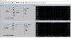
Brice -- Thank-you! If I may however, the one element that also absolutely needs to be included in your model is the .1 uF cap that would be connected across the output of the 47K network, as depicted when the damping control is turned to maximum. This cap has a huge impact on the response of the 47K track, and even affects the 15K track somewhat as well. It is this cap that is responsible for the 10 kHz response bump in the final design. But then to get a complete picture, you also have to consider the effect of the two step networks (the second being the most important), and Miller in the input stage for the updated design, versus the bypassed cathodes and reduced Miller in the original design. Finally, as you're scratching your head in trying to input all the different data, you realize that one track affects the other track as well. This is, a chosen track will measure one way with the other loop disconnected, and another with it connected. It can make your head explode if you let it. That's why with the data I provided (only to show trend), I made the 47K tract the standard that the other track was compared to.
Understand that I am hardly trying to throw stones or be critical of your modeling as I'm so old school, I couldn't even begin to approach doing it. Rather, I'm just trying to show how difficult it is to properly model a circuit for accurate results.
Dave
Brice -- Thank-you! If I may however, the one element that also absolutely needs to be included in your model is the .1 uF cap that would be connected across the output of the 47K network, as depicted when the damping control is turned to maximum. This cap has a huge impact on the response of the 47K track, and even affects the 15K track somewhat as well. It is this cap that is responsible for the 10 kHz response bump in the final design. But then to get a complete picture, you also have to consider the effect of the two step networks (the second being the most important), and Miller in the input stage for the updated design, versus the bypassed cathodes and reduced Miller in the original design. Finally, as you're scratching your head in trying to input all the different data, you realize that one track affects the other track as well. This is, a chosen track will measure one way with the other loop disconnected, and another with it connected. It can make your head explode if you let it. That's why with the data I provided (only to show trend), I made the 47K tract the standard that the other track was compared to.
Understand that I am hardly trying to throw stones or be critical of your modeling as I'm so old school, I couldn't even begin to approach doing it. Rather, I'm just trying to show how difficult it is to properly model a circuit for accurate results.
Dave