BASELINE EFB TESTING
The performance results presented here are for the fully restored 275 amplifier (before the application of EFB), that has been modified with:
1. New NFB and HF stability modifications with the Damping circuits removed,
2. Screen Stability resistors installed at both output tube sockets, and
3. Revised grounding scheme.
First however, a note about output tubes. The matched quad of coke bottle Tube Depot 6550 tubes were tried, with less than satisfactory results. Tests were then run on each tube in my power output tube tester, where one tube was found notably slow to warm up (and took a long time for the initial hum at turn on to balance out), and another was an eager beaver in terms of power output (the highest of all 8 tubes provided, and very near that of vintage American pieces). The other three however were dynamically close in terms of power output, but at a level some 8 watts below what an average new American 6550 can produce. The reduced power output capability shown in the tester explains why these tubes produced 7.5 less watts of power in the amplifier, and when the one eager beaver tube was used with any of the other three, clipping was unequal, and distortion appropriately elevated. These tubes also required almost 11% more bias voltage to reach a set current draw of 60 mA, or nearly 5 move volts of bias.
So, it was back to the Svetlana 6550C tubes (Wing C). They had been shipped in pairs, so originally I simply took one of the pairs, tested them, saw that they were reasonably matched and performing somewhat better than most Russian tubes of their day, and plugged them in. As is, the pair of Wing C tubes chosen were performing better than any combination of the Tube Depot 6550 tubes. But now that the unit was being base line tested for EFB, it is always best that the best output tubes be installed to see the widest variations produced in power supply voltages possible. With that then, the other pair of Wing C tubes were also tested and graded. It turns out that by picking one tube from each pair, a new pair of Wing C was made that had an extremely close dynamic match (basically identical) -- at a power output representing 94.12% of average new American pieces (down just 2.6 watts) -- and had a tight static match that is within 1.56%. These well matched and well performing tubes were installed to produce the restored but pre-EFB performance results provided from these tests. But first for comparison, a review of the amplifier's operation as it was before restoration (but with the three modifications listed above installed), with as many original (but still in tolerance) parts left in place:
POWER AND DISTORTION (distortion measured at 1 db below 60 watts output:
@20 Hz = 60.1 watts @ 1.55% THD
@1 kHz = 60.1 watts @ 0.32% THD
@20 kHz=54.4 watts @ 2.40% THD
IMD = 57.45 watts equivalent RMS @ 1.90%
FREQUENCY RESPONSE: 20 Hz - 20 kHz, +0/-0.1 db
@10 Hz = +/-0 db
@ 5 Hz = +/-0 db
@ 2 Hz = - 6.0 db
@ 40 kHz = -0.5 db
@ 50 kHz = -1.0 db
HUM AND NOISE:
-86 db below 60 watts.
SENSITIVITY:
0.45 vac for 60 watts
So the amplifier was hardly performing poorly, but the restored amplifier employs hand picked components that are not only within 1% of specified value, but where required, matched within 0.25% on either side of the push-pull circuit. At the time these components were chosen, components were also set aside for the other amplifier, so that it too will employ components within 1% of specified value, and within a 0.25% match on either side of the push-pull circuit. This will effectively match the performance of the two amplifiers very closely. The results for the first amplifier are presented now:
POWER AND DISTORTION (distortion measured at 1 db below 64 watts output)
@20 Hz = 64.0 watts @ 0.85% THD
@1 kHz = 64.0 watts @ 0.28% THD
@20 kHz=60.1 watts @ 2.70% THD
IMD = 62.1 watts equivalent RMS @ 1.45%
FREQUENCY RESPONSE: Essentially unchanged from data above.
HUM AND NOISE:
-88 db below 64 watts
SENSITIVITY:
0.47 vac for 64 watts
OUTPUT TUBE B+ SUPPLY:
With all chassis controls properly set, B+ dropped from 450 vdc under quiescent conditions, to 410 vdc at the onset of clipping at 1 khz. Under the same conditions, bias voltage dropped < 0.50vdc, causing a significant shift in the operating conditions. This shift is even greater at 20 Hz and 20 kHz.
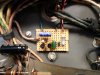
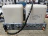
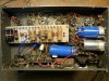
So the restoration and change in tubes added a few more watts, producing less distortion than before, and at a greater power output level. At 20 kHz, power and distortion are OPT limited at that frequency largely due to the sheer size of the output transformer. Distortion has risen incrementally at this frequency, as has power output as well, with the higher power output produced being responsible for the increase in THD noted at this frequency. This is quite insignificant. In any event, the measurements show an amplifier that is quite healthy in it's performance, but also one that just may respond very nicely to the addition of EFB, so work will begin on that next. As always, a few pics are provided.
Dave
Warming up for the testing process:
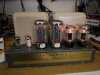
Everything nearly finished up:
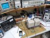
Final HF transient performance: 10 kHz square wave with standard resistive load. I see Scooter just had to leave a calling card almost dead middle of the screen.......