• Please note that Audiokarma will be offline briefly for updates early on Monday morning, September 28th.

Rare Beauty: Fairchild's 275 Amplifier

AMPLIFIER #2 CONFIRMATION CHECKS

Amplifier #2 was originally checked to insure the integrity of its transformers, but has now been restored enough to really roust it out of its who-knows-how-long slumber. Like it's mate previously addressed, the second can cap was hopelessly beyond any attempt to reform it, displaying an incredibly high power factor. The blue caps installed from some previous restoration effort could still be reformed, but since they were being replaced anyway, I decided to go ahead with that part of the restoration and replace all the can caps before powering things up.

Those following along might remember that I noted early on how the new bias caps that had previously been partially installed were installed with their polarity reversed in both units. But because these caps were grounded at the power supply ground point, correcting that problem also meant diving into the intermixed ground issues between the power supply grounds and the audio grounds (OPT Common lead grounded at noisy power supply ground at power transformer mount terminal rather than at audio ground point), so opportunity was also taken to install the new ground system as well. Finally, since new power supply caps were installed, opportunity was also taken to go ahead an install the Screen Stability resistors to protect the output tubes from any potential arc events arising from installation of the new can caps.

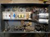
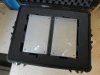
To allow for a proper operational start up, two of the old/new bias caps were temporarily tacked in place (polarity correct!), and proper hardware was used to mount the component tag board in place. This unit also arrived here sans a fuse and fuse cap, so a specified 4A fuse was installed via a correct fuse cap for the fuse post installed (secured earlier). Other than the points mentioned however, this unit still retains the updated circuit as installed by Fairchild. Collectively then, this work has amplifier #2 currently looking like this in preparation for its wake-up call:
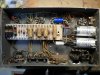
SAM_3017.JPG

The amplifier came to life quite uneventfully, with all chassis controls easily adjusting the output tubes to to an optimum setting. As previously noted, the 6AB4 input tube provided for this amplifier also had notable heater/cathode leakage, which ruins the S/N ratio performance in this amplifier as well. This will be resolved with new 6AB4 tubes for both amplifiers. Otherwise, measured performance for response, transient response, power response, distortion, and the like all validate that the performance as originally measured on the first amplifier, is in fact an accurate sampling of the performance that the design as built and produced by Fairchild is capable of. To that point then, this 10 kHz square wave should look very familiar to those who remember what a square wave of the same frequency looked like as originally produced by the first amplifier:
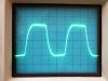
SAM_3018.JPG

So, the beat goes on. More updates as progress warrants.

Dave
 
SLIDING INTO HOME

But, not without a little detective work to effect that end. I offer up for your consideration:

SAM_3025.JPG

THE CASE FOR TESTING: Preliminary tests had shown that amplifier #2 would take well to the restoration work -- and it did, except that it's distortion performance was not meeting expectations pre EFB™, after everything else was finished. Previously, it was of note higher than amplifier #1 pre EFB, but nothing to cause alarm or that finishing the restoration wouldn't address -- except it didn't. Distortion remained stubbornedly higher, so that became a side road that needed to be taken before proceeding with the installation of EFB. Enter the two resistors above.

The top one is (by all indications) the original piece out of amplifier #1. This 3.3Ω 1 watt 10% resistor measures 3.37Ω. Since this is (basically) within 2% of target value, and because it only dissipates 0.25 watt (25% of rating) -- and this only under full sustained power output -- there was little reason to replace it. Now look at the bottom resistor.

This resistor appears to be a replacement installed at some point by the previous owner, as it is of a different manufacturing style than the top resistor. The solder connections for this resistor appeared to be non-original as well. In any event, this resistor measured 3.40Ω -- basically within 3% of target value -- and it was also within 1% of its mate in amplifier #1, so little need was seen to replace it, either. Except that the distortion problems were all pointing towards the output stage being the guilty party. Numerous tests were made that all came out negative, but one last test was devised to ensure that everything I thought was true, really was true.

This resistor is the one that the bias control is adjusted to develop a 0.5 volt voltage drop across to establish the proper quiescent current flow. So the test that was rigged up had the volt meter connected across the resistor as usual, but this time, a milliamp meter was also connected in series with the resistor/volt meter combo, as a double check of actual current flow. The amplifier was turned on, the voltmeter came up to a .5 volt reading (indicated a 152 mA current flow), but the milliamp meter only indicated about 105 mA. ??? The value of the resistor was rechecked (with two separate meters where it again displayed a resistance of 3.40Ω. The voltmeter function was also checked to no avail. So then the milliamp meter was then checked against a known current flow, where its accuracy was was confirmed as well. Everything was reconnected to the amplifier, where again, a 0.5 volt indication across the resistor only produced a measured current of 105 mA. The fact that the amplifier was producing more distortion than amplifier #1 also gave credence to the fact that the meters were right, but the resistor was junk.

New resistor were ordered, out of which two were chosen that were within 1% of target value, and 1% of each other's actual value. Since the new resistors were metal oxide, while the old ones were carbon composition, the resistor installed in the first amplifier would need to be changed out as well, since the temp coefficient of the metal oxide resistors is opposite that of the old carbon comp ones. The new resistor was installed, and everything reconnected for the same test. The bias adjustment hadn't been disturbed from the previous tests, so the amplifier was turned on. The milliamp meter again read 105 ma, but now, the voltmeter was reading just 0.343 vdc. The bias was adjusted to produce 0.5 vdc across the new resistor, and distortion fell to exactly mimic the first amplifier.

So under the current flow of an Ohmmeter, the problematic resistor measured just fine, and consistently so. And yet, with about 100 mA of current flow thorough it, it's value effectively jumped to almost 4.8Ω, or 45% greater than indicated value, which resulted in setting the quiescent current much too low, and the distortion being elevated as a result. I'm certainly aware that resistors have a voltage coefficient, but the voltage here is so low as to be insignificant for that. This one was a first for me -- I'd never seen anything like this before so it's just one more thing to be aware of with carbon comp resistors that have a significant current flowing through them. By the way, the stupid resistor still measures 3.40Ω out of circuit..........
________________________________________________________________________________________________________________________________________________________________________

Moving on then, amplifier #2 is now all finished up, EFB installed, and the chassis controls set. Also, the new 3.3Ω resistor mate was installed into the first amplifier, and its chassis control settings rechecked. Both amplifiers are now (finally!) being moved over into the listening room to start listening and dependability testing which will be in my next post. For now however, a few pics:

Below: The second amplifier is all finished now, being almost identical to the first in every detail -- both in build and measured performance. About the only way you can tell them apart physically from this view is that the previous owner in his service efforts removed the black cable thread bundling the leads going to the rear controls and output connections in the second amplifier. Otherwise, this amplifier has a white input jack, while the first one has a red, and that's about it:
SAM_3022.JPG

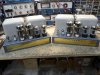
Below: Both amplifiers together, where the near identical finished appearance can be seen:
SAM_3023.JPG

Below: Ready for transfer to the listening room. My client sent a veritable plethora of output tubes to test both in my PO tester and the amplifiers, be it Wing C 6550Cs, reissue Tung Sol 6550s, original (used) Tung Sol 6550s, and new reissue Genalex KT88s. And the winner is:
SAM_3024.JPG

Final comments and observations after the listening and dependability tests are finished, which should wind up this weekend. This should be fun!

Dave
 
Last edited:
Pesky little buzzards those carbon composition resistors.

What? Original Tung Sol 6550s didn't stomp everything else? Who woulda thunk? Unless the original Tung Sols were just flat worn out.

Man I wish I could hear those amps!
 
Really odd CC behavior. Usually they test higher than rated when they are turning.

You probably pulled the remaining hair of your head with that one. :)

Thanks for sharing and the rest too.
Brice.
 
Huh, haven't run into that CC behavior either that I'm aware of. Usually they just test so far out to lunch with common means that I never had reason to investigate further. Now I'm curious. Next time I come into a batch of them perhaps I'll do some ohm meter checks and then some under load checks to see if it acts differently.
 
I remember reading Kiebert's 1952 article on "Improving the Williamson" and being struck by his mention of how awful the first test sounded--a rather unusual remark from an experienced EE--until he replaced the CC resistors in the feedback network with 1 watt wirewounds. In fact, the first Williamson I ever laid eyes on, a hefty homebrew version, used bobbin-wound resistors in those two positions.
 
SLIDING INTO HOME

But, not without a little detective work to effect that end. I offer up for your consideration:

View attachment 1864001

THE CASE FOR TESTING: Preliminary tests had shown that amplifier #2 would take well to the restoration work -- and it did, except that it's distortion performance was not meeting expectations pre EFB™, after everything else was finished. Previously, it was of note higher than amplifier #1 pre EFB, but nothing to cause alarm or that finishing the restoration wouldn't address -- except it didn't. Distortion remained stubbornedly higher, so that became a side road that needed to be taken before proceeding with the installation of EFB. Enter the two resistors above.

The top one is (by all indications) the original piece out of amplifier #1. This 3.3Ω 1 watt 10% resistor measures 3.37Ω. Since this is (basically) within 2% of target value, and because it only dissipates 0.25 watt (25% of rating) -- and this only under full sustained power output -- there was little reason to replace it. Now look at the bottom resistor.

This resistor appears to be a replacement installed at some point by the previous owner, as it is of a different manufacturing style than the top resistor. The solder connections for this resistor appeared to be non-original as well. In any event, this resistor measured 3.40Ω -- basically within 3% of target value -- and it was also within 1% of its mate in amplifier #1, so little need was seen to replace it, either. Except that the distortion problems were all pointing towards the output stage being the guilty party. Numerous tests were made that all came out negative, but one last test was devised to ensure that everything I thought was true, really was true.

This resistor is the one that the bias control is adjusted to develop a 0.5 volt voltage drop across to establish the proper quiescent current flow. So the test that was rigged up had the volt meter connected across the resistor as usual, but this time, a milliamp meter was also connected in series with the resistor/volt meter combo, as a double check of actual current flow. The amplifier was turned on, the voltmeter came up to a .5 volt reading (indicated a 152 mA current flow), but the milliamp meter only indicated about 105 mA. ??? The value of the resistor was rechecked (with two separate meters where it again displayed a resistance of 3.40Ω. The voltmeter function was also checked to no avail. So then the milliamp meter was then checked against a known current flow, where its accuracy was was confirmed as well. Everything was reconnected to the amplifier, where again, a 0.5 volt indication across the resistor only produced a measured current of 105 mA. The fact that the amplifier was producing more distortion than amplifier #1 also gave credence to the fact that the meters were right, but the resistor was junk.

New resistor were ordered, out of which two were chosen that were within 1% of target value, and 1% of each other's actual value. Since the new resistors were metal oxide, while the old ones were carbon composition, the resistor installed in the first amplifier would need to be changed out as well, since the temp coefficient of the metal oxide resistors is opposite that of the old carbon comp ones. The new resistor was installed, and everything reconnected for the same test. The bias adjustment hadn't been disturbed from the previous tests, so the amplifier was turned on. The milliamp meter again read 105 ma, but now, the voltmeter was reading just 0.343 vdc. The bias was adjusted to produce 0.5 vdc across the new resistor, and distortion fell to exactly mimic the first amplifier.

So under the current flow of an Ohmmeter, the problematic resistor measured just fine, and consistently so. And yet, with about 100 mA of current flow thorough it, it's value effectively jumped to almost 4.8Ω, or 45% greater than indicated value, which resulted in setting the quiescent current much too low, and the distortion being elevated as a result. I'm certainly aware that resistors have a voltage coefficient, but the voltage here is so low as to be insignificant for that. This one was a first for me -- I'd never seen anything like this before so it's just one more thing to be aware of with carbon comp resistors that have a significant current flowing through them. By the way, the stupid resistor still measures 3.40Ω out of circuit..........
________________________________________________________________________________________________________________________________________________________________________

Moving on then, amplifier #2 is now all finished up, EFB installed, and the chassis controls set. Also, the new 3.3Ω resistor mate was installed into the first amplifier, and its chassis control settings rechecked. Both amplifiers are now (finally!) being moved over into the listening room to start listening and dependability testing which will be in my next post. For now however, a few pics:

Below: The second amplifier is all finished now, being almost identical to the first in every detail -- both in build and measured performance. About the only way you can tell them apart physically from this view is that the previous owner in his service efforts removed the black cable thread bundling the leads going to the rear controls and output connections in the second amplifier. Otherwise, this amplifier has a white input jack, while the first one has a red, and that's about it:
View attachment 1864081

Below: Both amplifiers together, where the near identical finished appearance can be seen:
View attachment 1864087

Below: Ready for transfer to the listening room. My client sent a veritable plethora of output tubes to test both in my PO tester and the amplifiers, be it Wing C 6550Cs, reissue Tung Sol 6550s, original (used) Tung Sol 6550s, and new reissue Genalex KT88s. And the winner is:
View attachment 1864105

Final comments and observations after the listening and dependability tests are finished, which should wind up this weekend. This should be fun!

Dave
A lesser tech would have never caught that. Such an explanation is the cornerstone for my repeatedly discouraging those without any electronics skills from attempting to "repair" their own stuff. Well done.
 
Mac -- Thanks for the kind words. It had me going for sure for the better part of a day (try something, then ponder the results, try again, etc.). Like all the comments made by others, I'd never seen anything like it. I should also mention that I also tested the resistor from the first amplifier to check for the same effect -- but it was solid as a rock, even as current flow was increased beyond quiescent to maximum power output. Indicated current by voltage drop across the resistor was always in agreement with actual measured current in the circuit. A strange one for sure.

Brice -- In a way, it did act exactly like a CC resistor: It's value did grow, but you didn't know it until performing the alternate test with enough current was passing through it to prove that out. Maybe I just caught it in the act of so to speak, such that with further use, the resistor would permanently change state. Further testing showed that the deviation (or true character of the resistor) first started showing itself with as little as 10 mA of current flow -- which is still way, way more current than even an old VOM would pass through it during testing. But the jump in value happened quickly enough, as well before passing even 15 mA, the change in value would fully take place, with the effective value of the resistor again indicating virtually the same as before -- nearly 4.8Ω -- even at this greatly reduced current flow, as compared to the original test made at 105 mA. So once the value jumped, it then held constant once the jump was made -- but man oh man, what a goofy resistor it was!

K -- The original Tung Sol 6550s were no slouch. In fact, even with physical signs that showed significant use, they still won the horsepower race, and still continued to produce greater power output than the ANPO (average new power output) level established for 6550/KT88 tubes in my power output tube tester. The thing is however, the new Genalex KT88 is also an exceptional tube. The darn things look very much like the original, and for all intents and purposes, perform exactly like the original as well. I have a some nice matched pairs of original Genalex KT88 tubes (used, but still very, very good), and at least in terms of measured qualities (power output, distortion, bias stability, clipping characteristics, etc.), the Russian reissues are right in the hunt with them -- to the point that without looking, you wouldn't know if it was Memorex, or the real thing (the new versus the old for you youngsters). To my mind, the only undetermined quality about them is their life expectancy versus the original. To that point, I've got nearly 1000 hours on a quad now that show no signs of fatigue.

Of the bunch, the Tung Sol reissue was (for me) the biggest disappointment, looking very much like the originals, but also performing like so many of the early Russian tubes -- only capable of producing about 82-85% of ANPO at best in my PO tester, and according to my client, these tubes were all but brand new. In the amplifier, these tubes only allowed it to produce 50 watts of power -- well off the mark of all the other tubes.

Now the Wing C tubes -- when they were released -- represent (in my experience) a changing day for Russian manufactured tubes. First appearing what, 15 years ago (or so), Svetlana sent me some samples of their (at the time) 6550B (horrible) and 6550C tubes for comparison and evaluation. By comparison, the new C version was a very decent effort (compared to anything else available at the time) to copy the original pieces -- and night and day over their previous B offering. They've never looked like the original piece, but at least their performance was no longer a joke. The thing I have noticed regarding them however since that time, is inconsistency. As I've come upon them, some come off as the serious effort they are intended to be, but some don't. And so it is with the four examples sent with these amplifiers: Two are very well matched, and perform quite well. The other two come off like the TS reissue tubes. Now all of these tubes are quite stable in the amplifiers (which early Russian tubes were anything but), but beyond that, the differences are notable.

Against these experiences and knowing my client's desired outcome for the project, after reporting to him the testing results of the Wing C, TS reissue, and of his original 6550 tubes, I recommended that for his goals (daily drivers with maximum performance, maximum dependability, and significant use), the Genalex reissue would be my choice, and the examples he purchased (from Upscale Audio) continue with my impression of these tubes, again not failing to impress. So the original TS 6550s performed very well indeed, and particularly so for the obvious amount of time on those tubes -- but that is hardly uncommon for the original devices. I've seen numerous examples of those darn things looking all beat to hell and they still produce ANPO for the tube. Their legendary status is well deserved. For a modern replacement however -- for any 6550 or KT88 application -- it is my experience that nothing comes close to the reissue Genalex KT88. So considering that their performance is indistinguishable from the original TS tubes in these amplifiers, and considering my client's plug-em-in-and-forget-about-em goal (dependability wise), these tubes get the nod.

I was going to go over all of this (among other things) in my final comments on the amplifiers, but since you asked now, I just took the opportunity to check those comments off ahead of time. I've included a pic of the original TS tubes sent, so you can see the notable use time they indicate.

Thanks to all for following along!

Dave

SAM_3026.JPG
 
I remember reading Kiebert's 1952 article on "Improving the Williamson" and being struck by his mention of how awful the first test sounded--a rather unusual remark from an experienced EE--until he replaced the CC resistors in the feedback network with 1 watt wirewounds. In fact, the first Williamson I ever laid eyes on, a hefty homebrew version, used bobbin-wound resistors in those two positions.
Wouldn't there be an inductance element added to the FB loop with bobbin wound resistors replacing CCs?
 
Really odd CC behavior. Usually they test higher than rated when they are turning.

You probably pulled the remaining hair of your head with that one. :)

Thanks for sharing and the rest too.
Brice.
Verrrry interesting indeed!
I have wondered about resistors that measure consistently in tolerance, but shift or collapse under current carrying load.
I have an early Marantz 8 with a mystery HF stability problem in one channel that has evaded diagnosis, with current carrying CCs in the phase splitter. I wonder if this could be a possibility.
 
SETUP OBSERVATIONS

In the listening room, while setting up the amplifiers for listening tests (using 100db Cornwalls), you always learn things that the lab doesn't always (or can't) disclose, because now the amplifiers are interconnected with other pieces of equipment and become part of a team. Various observations (including final ones from the lab) include:

1. Fuse -- The first amplifier came with a complete fuse post and (by all accounts) original fuse. The second amp was missing the fuse and fuse cap. The schematics and silk screening all indicate use of a 4A fuse. When the second amp was first first fired up from direct AC line power, the 4A fuse I had installed immediately blew. I wasn't particularly worried, as the transformer had already been brought up by variac, where it displayed no problems. A peak back at the first amp showed that it's fuse was a 4A Slo-Blo type, of the manufacture style commonly seen in the 50s and offered as original equipment pieces (hence the belief it was an original device). Installing a 4A Slo-Blo fuse in the second amp has produced no failure re-occurrences.

This is hardly unusual. The core of a power transformer will remain in the state of flux it was in at the moment it was turned off. The power transformers on these amplifiers are quite large, and so course then also is the amount of flux they create. If a large power transformer therefore happens to have its power removed when the AC power is at one crest, and then reapplied at a later time when the AC power is at the opposite crest, then the current surge created at turn on by the core alone can be very high, and is the usual reason that larger amplifiers can blow a fuse for no other apparent reason. When such events happen, they are always instantaneous at the moment power is applied, and produce a notably violent "blow" of the fuse, which is exactly what happened. For the 275 then, a Slo-Blo version of the specified 4A fuse is appropriate.

2. AC Voltage Selection -- The 125 volt primary tap produces proper heater voltages and B+ levels that agree with Fairchild schematic voltages for a typical line voltage of 121-122 vac. This is the voltage tap used throughout the entirety of the project.

3. Chassis Adjustments -- Since the setting of the Grid and Current Balance controls are based on adjusting for minimum hum, the procedure changed slightly after the revised ground configuration for noise reduction was implemented. The final procedure that produced the best results is as follows:

A. Start with all 3 controls mechanically centered, all tubes installed, and monitor the output with headphones or a close range sensitive speaker.
B. Adjust Current Balance for min 120 Hz hum.
C. With DC voltmeter connected to a 1/4" phone plug (tip+) and tip of phone plug inserted just enough to make contact but not lock into place, adjust Bias control for a reading of 0.50 vdc.
D. Remove 12AV7 tube and push 1/4" phone plug in until it locks. Adjust Grid Balance control for min 60 Hz hum. Remove phone plug and reinstall 12AV7.

The controls are of course somewhat interactive, so the procedure will need to be repeated until optimum settings are achieved for all three controls. The procedure should be performed when tubes have initially warmed up (about 40" from turn on), and monitored throughout the full warmup period (about 15 minutes). Adjustments made after the amplifier is fully warmed can be considered as final.

4. Magnetic Coupling -- Normally, when such a large power transformer and output transformer are located in such close proximity on a chassis, there is usually some degree of coupling -- even when the poles of the transformers are positioned to minimize such coupling. In practice, this is evidenced in the speaker as a low level hum the instant the amplifier is turned on, which then disappears when the output tubes draw current to prevent the coupling. In the 275 however, there is absolutely no notable coupling between the transformers to produce a low level hum when the amplifier is first turned on. The speaker (or headphones!) is/are utterly silent, which is really quite amazing.

5. Warmup Behavior -- As is typical of designs with marginal B+ filtering, the amplifiers will announce themselves when the output and rectifier tubes begin to conduct. Unless the warmup characteristic is identical between the two output tubes (that period of going from no conduction, to a stabilized balanced conduction between the two tubes) -- which rarely happens -- the speaker will announce the presence of the amplifier coming to life with a notable 120 Hz hum in the speaker. The hum quiets itself quickly enough (in about 10-15 seconds) to be inaudible from even a close listening position, and is clearly the result of having no second stage of filtering before supplying B+ to the output stage. Now whether Fairchild was trying to minimizes the effective power supply impedance before the output tubes (which certainly has its benefits), or just thought it was a non issue (and in a large venue or with inefficient speakers it likely is), we'll never know. But with highly efficient speakers in a quiet residential setting, the hum is present if only for a few moments at turn on. It also emphasizes the fact that proper output stage DC Balance is a matter of some importance for quiet operation of these amplifiers.

6. Sensitivity -- Back in the day, amplifiers and preamplifiers were designed so as to be compatible with virtually any make or model amplifier/preamplifier from another manufacturer. As a result, we ended up with a majority of preamplifiers having a line stage gain of around 20 db (X10), and a a number of power amplifiers with an input sensitivity of around 0.5 vac to produce full power output -- of which the 275 is one.

I have long felt that there is simply no need for an amplifier of the 275's power output capability to be that sensitive. Yeah, an input level control can match the amplifier's sensitivity to the associated equipment, and if the level control is designed properly (which it is in the 275), its setting will have little to no impact on the HF response of the amplifier. From this standpoint then, it's all good with the 275. My installation is (admittedly) a worst case scenario for these amplifiers: with the normal 2 volt output of my Denon DCD-1520 CD player somewhat attenuated (to about 75% output), and using my Fisher 400C preamp and Cornwall speakers, the level controls on the 275s had to be backed down to about 25-30% of their full setting to reduce preamp noise appropriately, and produce normal volume control action.

More to the point then, while a well thought out input level control can properly address the sensitivity issues within a given system, it cannot make up for the noise generated by the excess gain produced within the power amplifier chassis. With the bottom covers installed, these amplifiers now achieve a -90 db S/N ratio -- which for amplifiers of this power and sensitivity level is remarkable. If the 7 pin tube socket for the 6AB4 had been provided with a tube shield, it could be even better. But even with the best precautions taken, the excess gain still aggravates issues of lead dress, ground configuration, and input tube selection (all items requiring attention with this project) within the build of the amplifier, in trying to achieve optimum S/N level performance. This is hardly meant as a complaint against the design as implemented by Fairchild. Back in the 50s, when sensitive speakers reigned king and the dynamic range and S/N ratio of LPs was nothing compared to today's digital sources, nobody in their right mind would've teamed up 120+ watts of Fairchild amplifier in a smallish (and quiet) 15X20 listening room with this kind of equipment. But of course today, anything goes. So the idea of mix and match takes on a whole new meaning -- and can produce a whole new set of problems as well.

Where I'm going with this is that I think one area of opportunity with these amplifiers is to redesign the input stage and NFB loop to use a 6C4 (1/2 of a 12AU7) tube rather than the specified 6AB4 (1/2 of a 12AT7). They are both 7 pin tubes of virtually identical physical size and similar pin out, but the 6C4 has about 1/3 the gain of the 6AB4, which with all else remaining equal, would push the sensitivity of the amplifier up into the 1.5 volt range, which is much more practical for an amplifier of this power level. The basic sonic qualities of the design would be maintained, being principally established by the amount and stability of the NFB applied, resulting transient performance, and use of a tapped screen grid output stage. Of course, that would be another deviation of the original design, so it's something I'm hardly pushing for or suggesting would be an improvement beyond the improvement in S/N ratio produced. But, it would provide for an even quieter amplifier, allow for the elimination of the level control (if desired) which is always a possible point of signal deterioration, and make the amplifier's sensitivity level more appropriate for use in today's audio environment.

Collectively then, these are the final lab observations, and observations made during set up of the amplifiers in the listening room in preparation for the listening tests. Those results will be in the final post on the project.

Dave

Ready to go!
SAM_3030.JPG

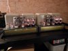
Even at 32 watts of plate dissipation, the Genalex KT88 reissues are cool customers as this time exposure shows, ultimately reaching about 300˚F each after 2 hours of operation, even in the rather close quarters they are mounted in. During the same time frame, the top, sides, and back of the power transformer finally topped 100˚F, all as starting from an ambient room temp of 70˚F.
SAM_3027.JPG
 
LISTENING IMPRESSIONS

All of my above comments notwithstanding, one satisfying results of all the work is that the amplifiers -- other than being differentiated by one having a red input jack and the other a white -- are utterly identical sonically -- always a challenge when using mono blocks for stereo operation. One often has a telltale difference to identify it from its mate -- but not so in this case. The amplifiers can be mixed up in shell game fashion, and you won't know which is which when listening. The other point to emphasize is that in my listening room with the equipment used and adjusted as described earlier, the amplifiers do not inject any discernible noise from the speakers as observed at my listening position some 14 feet in front of the speakers. Tone controls were all set at flat, and only CDs were used since it was power amps being considered, and not the preamp or its sources.

As to my listening impressions, I've divided the material I used into three different categories to individually assess bass, mid-range, and high frequency performance. I find that easier than trying to assess each sector from each recording. All sectors are certainly observed on each recording, but some recordings are more challenging that others in certain sectors, and can therefore be used to zero in on performance in a given sector. I've listened over a period of 3&1/2 days, sometimes for short periods, sometimes quite extended, over a course of morning, noon and night -- this to try and minimize as much as possible the human influence on the impressions made. The listening level was also varied, over the period, with the Loudness function used on my modified Fisher 400C preamp (so as to mimic the performance of the 400 CX-2) when the listening level was low.

For BASS performance, I used four recordings:
1. Telarc's recording of the 1812 Overture
2. Telarc's recording of Michael Murray on the organ at Symphony Hall in Boston.
3. Julian Vaughn's "Breakthrough" album.
4. Telarc's Saint Saens Symphony No.3 "Organ"

These are all particularly challenging recordings to reproduce relative to their LF content: The digital recording of authentic 19th century cannons in the Overture has the "crack" of the explosion taking place in the 2-3 kHz range. But the "boom" -- fully captured digitally has strong content going down as low as 6 Hz. In the vinyl version of Telarc's release, you can literally see the cannon cracks in the grooves as near right angle turns, that will cause very, very many tone arms to simply jump off the record. Speakers that are less than capable of the material can literally have their voice coil assemblies physically blown out of the magnet assembly on the cannon shots. The Aeolian-Skinner organ at Symphony Hall has 32 ft pipes that when pressed, you feel rather than hear. It's easy for such LF information to either turn to mush when reproduced (lack definition), or inter-modulate with the presentation from higher frequency pipes. Bassist Julian Vaughn challenges the capabilities of recording and reproducing equipment alike, with playback equipment needing to be able to reproduce distortion in the recording process, without introducing any of its own. There are few words to describe the Saint Saens piece, as words simply do not do it justice. For realistic presentation, only the best need apply. The organ's grand entrance is commanding, building to an end with timpani and bass drum that easily requires (a measured) 50+ watts of peak power per channel for proper reproduction -- and this with Cornwalls!

In the bass register, this is where the 275 excels. It takes any LF information you throw at it, and takes it in perfect, but rather ho-hum stride. Combined with the Cornwalls, the cannon shots -- at realistic levels -- come off as authentic rather than recorded. There is never any intrusion by the cannons into any other instrument in the recording, including the carillon bells. Everything holds it's place, and is reproduced as well as if the cannon shots were not part of the material at all. In Widor's toccata, the lowest pipes retain their definition, never running into each other, or getting lost as can so often happen with large amount of LF organ material. The character of each pipe and its own distinctive resonance in the hall is easily distinguishable from the other LF pipes, allowing enough of the frequency to be heard, to add definition to what is felt. With Vaughn's recording, the limits of the recording process are clearly distinguishable, but the 275s faithfully reproduce it without inter-modulation with the other instruments. With a dual bass presentation (his as well as that from the studio band), the energy level can be intense on his recordings, but again, these amplifiers take no notice. His notes are clearly delineated from that of the other bassist, so as with the Widor organ presentation, there is no mush -- which any of these pieces can do to amplifiers of lessor capabilities. Finally, the final bass drum roll in Saint Saens piece is not something you hear so much as feel. Realistic reproduction requires amplifiers of sufficient grunt, available on demand for an extended period. The 275s handle this with ease, leaving the rest of the instruments in tact and well defined. If music stirs you're emotions, be ready......

Of course, consider too that it is in the bass region where the EFB™ modification is most effective, since bass energy places the greatest demand (and particularly time extended demand with organ material) on the power supply, and therefore has the greatest impact on the output stage's operating point. EFB accounts for any changes in output stage operation due to additional power supply loading, adding icing on the cake to the 275's inherent and generous drawing board LF capabilities.

For MID-RANGE performance, there are two elements I look at in assessing this sector: how well a piano is reproduced, and the female voice. Both contain nuances that are very hard to reproduce accurately. The recordings I use here include:
1. Benny Andersson Piano
2. Various ABBA pieces
3. Come On Come On album (Mary-Chapin Carpenter)
4. Rachmaninoff Piano Concerto No.2 Chicago Symphony Orchestra

For Piano, the Andersson piece is one of the finest I have ever heard. A superb close mic recording that even captures the mechanics of the piano itself beyond the complex tones and resonances of the strings and sounding board. With the Rachmaninoff recording, you can almost hear each vibration of the piano strings in the opening of the piece. Not as closely miked, but still rich in detail. The clarity of definition is unsurpassed, and is maintained whether a single note, a chord, or the full keyboard is engaged. Andersson of course is the musical genius behind the music of ABBA, a well accomplished pianist many times over, but for female vocals, this is where the voice of Agnetha Faltskog enters the picture -- the soprano member of the group. She is nothing short of a power house that can belt it out with the best of them -- so much so that in the recordings of the band, she can come off as almost shrill at times given half a chance if the amplifier is so inclined. In contrast, Carpenter's voice is very full and lush, with plenty of detail on this particular album. All of these pieces put an amplifier's transient capability on full display, as poor transient capability translates directly to poor details with these pieces.

With the piano pieces the transient stability of the amplifier allows each note to have it's own space, well defined, without running into the other notes. On these pieces, the 275 brings you as close to being there as the recordings allow -- and they allow alot. These are both very live recordings that capture all the energy of the recording venue, and the 275s handle the detail generated with all the clarity and finesse that would be expected of these amplifiers.

With the vocal pieces, the detail in Carpenter's "I am a Town" is almost haunting (close your eyes and she's in the room), while ABBA's "Knowing Me Knowing You" is primarily Frida's song, but Agnetha is belting out the high notes behind her with such power that it can get away from amplifiers without a stable HF transient response. In both of these pieces, the Fairchilds did not fail to deliver, with all the detail, but never a harsh or sibilant tendency at all.

For HIGH FREQUENCY detail, I use any and many of the various Rippington releases, as these recordings are riddled with high frequency detail from both electronic and acoustic sources. All are superb recordings that include cymbal taps, triangles, and chimes which all come through with absolute clarity of transient detail and tone.......

All of which is to say that these 275s are extremely well balanced audibly in presentation, and because of their close matching, the sound stage created is quite large and wide. The amplifiers are extremely dynamic, producing that effortless sound that simply makes them disappear within the makeup of the system. They never draw attention to themselves in terms of limitations, or going about what they do, regardless of the material they are passing. They simply do what they do, and do it extremely well. Along with that, they are also extremely listenable, with zero listening fatigue even after many hours of use. More than that would be hard to ask for!

Dave
 
Hi Dave,

This is impressive.
I am sure may of us wished we could have been in that room when the listening session took place.
Have you measured the PT temperature after several hours of use? Just curious.
Thank you.

Brice.
 
Bone stock. I realized long, long ago that I didn't have the facilities, equipment, or even the proper understanding to properly assess -- let alone modify -- speakers, to "know" that anything I was doing actually represented a true improvement in performance. So the meager efforts I did try I long ago abandoned (40 or so years ago) -- and happily so. I'll never forget the first time I heard a pair of Cornwalls (1984), and immediately fell in love with them. That's not to say I haven't auditioned or listened to other speakers -- I have. But none have given me pause to even come close to replacing what I have. From a "sound" standpoint, the closest speaker I've heard that comes close to the Klipsch is the mighty AR-9s -- wonderful speakers, but they take true space heater energy to power, and again, the difference just wasn't that great to my ears to warrant a change, let alone the power they would require.

I do check the caps in the crossovers from time to time, and have replaced a couple as necessary -- but always with original component value and composition. I just sleep better at night leaving that aspect of the audio chain to others!

Dave
 
I have a few good Telarc all digital recordings from the mid 80's. During that era Telarc used no compression or limiting with the use of their Soundstream digital recorders. Lesser speakers and amplifiers need not apply when reproducing some of their excellent recordings at life-like levels. One album, "The California Project - Papa Do Run Run" (a Beach Boys tribute album) being one good example of this recording style. This recording is STILL one of the best I have ever heard, either in digital or analog formats, and I expect the 1812 Overture is in the same league.
 
@dcgillespie - how do you think the Fairchild compares to your custom W4-AM amplifiers (realizing that's a bit of an apples to Easter eggs comparison)? Two different approaches to push-pull from the early 1950s?
 
EPILOGUE

The Fairchild's arrived here 7 weeks ago (4-1-2020) and got mailed back to their owner earlier today. Besides the active work of the project itself, the amps have been here long enough to ponder and think about them as a back of mind exercise, as I always like to study and learn all I can about a piece I'm working on, and try to determine why the manufacturer chose to do things the way they did.

Lots of things were happening in 1956 on the audio scene. The 6550 had just been released a few months earlier. Ultra-Linear operation had virtually all but wiped out the commercial viability for any notion of conventional triode operated output stages, and manufacturers were still struggling with how to make a high performance, high stability, NFB amplifiers. The last issue entangled models from many a manufacturer back in the day -- be it Heath, Eico, Fisher, Grommes, and at least with the 275, Fairchild -- and there were surely other manufacturers as well. These are just the ones whose models I've had direct contact with. It was likely a more common problem than not at that time. So into this fray Fairchild jumped.

Stage center of these amplifiers is of course their transformer set, and they are really are superb pieces. The power transformers can run for many hours on end never even reaching 120˚F, and the output transformers can handle the full mid-range power of the amplifier at 20 Hz, being down less than 1 db at 20 kHz, and all with very low distortion. There is equal supersonic performance on all three output taps, and the ringing of the amplifier under feedback conditions is nil. For such a large transformer, this is truly impressive performance. They remind me more than a little of the performance displayed by the transformer set in the Fisher 50A, which should really come as no surprise since both of these transformer sets were designed by Todd Transformer Corporation. And, like the 50A, the Fairchild achieves excellent performance with only a moderate amount of NFB applied (275 = 14 db with my modification developed with this project, 50A = 12 db with my NFB modifications developed for that amplifier). This level of NFB makes both of these amplifiers very listenable, without any significant listening fatigue, which is a tribute to the caliber of the transformer designs used. Higher feedback levels required with lesser transformers tend to (but not always) make for a more clinical sound that limits listener engagement with the music.

Whether the Fairchild draws from other designs, or other designs draw from the Fairchild, who knows -- but the prize for having a cathodyne phase inverter directly drive a pair of UL connected 6550 output tubes would seem to go to Fairchild. Dynaco had already been driving EL34s that way in their MK II model, but 6550 tubes require notably more drive voltage, and at lower impedance levels. I know of no other design doing this right out of the gate with the 6550 when it was first made available. And, like the Dynaco design, the inverter is direct coupled from the previous stage, but that stage being the other half of the 12AV7 dual triode eliminates all the problems of plate voltage inconsistency, and has far less potential for heater/cathode hum than Dynaco's pentode/triode arrangement has. The 12AV7 tube was designed as an RF tube however (as was the 6AB4 used in the input stage), so these tubes can be prone to noise in general, but at least with the 12AV7 being a Medium Mu tube, any noise it generates is not nearly so objectionable compared to that which a High Mu 12AT7 tube can produce -- which was also primarily designed as an RF tube as well. The 12AV7 wasn't actively used very long, being rather quickly moved to the "not recommended for new design" status. It's a pretty darn capable tube however, basically being a 6BK7B with a 12.6 volt heater option. This latter tube lasted all throughout the tube years however, so if the 12AV7 tube ever becomes an endangered species, the 6BK7B could be used with little more than changing the heater wiring to the socket -- and, it's plentiful and inexpensive.

As designs go, I always tend to favor those using triodes in the small signal stages -- with the EF86 being the near lone exception. It's not so much a sonic thing than it is that with triodes, circuit operation is just more consistent from tube to tube, so the 275s were already appealing to me based on that reason alone. I also generally prefer audio intended tubes for audio applications if only to eliminate the issue of finding quiet tubes, which I had to deal with regarding the 6AB4 (1/2 of a 12AT7 RF tube) in this project. I finally had to purchase a small lot of them to find two quiet, matched tubes for these amplifiers, and then return the unused tubes. A 6C4 and 6CG7 would deliver the same performance capability in this design, are consistently quiet tubes, and would address the sensitivity issue to boot.

Tapped screen grid operation of the output stage is about as good of an overall compromise as you can make between true triode and pentode operation of the stage. Triodes don't develop much power at traditional operating voltages, but produce primarily 2nd order distortion, and have a wonderfully low output impedance. Pentodes produce gobs of power, but with higher order distortion, and very high output impedance. Tapped screen operation capitalizes on the best of both worlds, being optimized at a UL specified tap point for the tubes being used. It is without a doubt the easiest way to achieve excellent output stage performance. With pentodes you can go the McIntosh route to optimize performance, or with triodes, you can go the Class AB2 route that Fisher blazed, and both produce really excellent results when implemented correctly, but both are also more costly to execute than UL. With this project, it was interesting to see the excellent performance that the 6550/KT88 tubes returned when using a 25% tap point. Tubes of this class typically operate with 33% at a minimum, and typically with a 40% tap point. The KT88 is known to be rather flexible with regards to tap point, while the 6550 is understood to be more rigid in it's requirements. The 275 however shows how versatile it is as well, which was a pleasant surprise.

The power supply in the 275 is as wonderfully heavy duty, as it is sparse filtering wise. As a result, maintaining an optimum output tube balance is critical in achieving low noise. However, unlike so many (later to come) 60 watt amplifiers using UL connected 6550s, the 275's dual rectifier tubes minimize voltage drop with increasing power output, and maximize tube life. It also runs quite cool as well. For all the excellent qualities it has however, the power supply -- after correcting the NFB/HF stability circuits -- is the area of biggest opportunity in these amplifiers. It might be possible to move the component tag board closer the tubes and possibly allow room for a choke, but I don't know if it could be orientated properly or not relative to the power transformer to minimize any coupling between the two devices. While it would ease the tight output tube current matching requirements, the GL KT88 reissue tubes seem to hold their balance well enough -- I never found the need to constantly fiddle with the current balance adjustment for the tubes. And of course, having no filtering resistance in the output tube B+ circuit keeps power supply impedance to an absolute minimum, which was no doubt Fairchild's goal.

There's more than a little reason that I found myself comparing these amplifiers to Fisher's 50A. Both are radically different in their approach to what they do, yet both return a very very similar sonic performance. This comment relates of course to the modified 50As I've restored, and the modified 275s here. Consider:

1.The 275 has a little more grunt (horsepower) than the 50A -- but rather insignificantly so. The FET based Bias Regulator I devised for the 50A added power output to that model, and reduced distortion to lower levels than the stock design produced at lower power output. For the 275, EFB™ didn't really add any horsepower, but did cut distortion levels in half versus that of its stock design. In both cases then, output stage performance was optimized.

2. Both designs use triodes, or triode connected tubes in the small signal stages.

3. Both models had their NFB systems completely reworked to produce excellent HF transient stability and frequency response, as well as excellent load stability.

4. Both designs employ heavy duty dual rectifier power supplies.

5. Both designs employ Todd transformer sets, and use only a moderate amount of NFB to achieve very good performance.

So even though one uses tapped screen grid operation of modern tubes to achieve high power output, and the other uses a never-to-be-seen-again (other than by Fisher) Class AB2 Triode output stage to achieve high power, they both sound remarkably if not nearly identical. Derekva asked how they sounded next to my EL34 Triode Williamson design. Answer: virtually the same, except without the grunt reserve. All of which is to say that there's more than one way to skin a cat -- and, that designed properly, very different designs can sound virtually the same if engineered to the same high level of performance expectations.

Oh, and one last thing to be total fair to the Fairchilds: The warmup hum I noted, was found to be notably due to the GL KT88 tubes. While they look, act, and perform virtually the same as the originals in every way, there is one way that they don't: Warmup time. The characteristics of the heater in the original 6550 is such that they have a tremendous cold turn on surge, but warm up rather quickly. The new GL reissue tubes have a greatly reduced turn on surge, but warm up rather slowly. The result is that the old stock 6550s warmed before the 5V4 rectifier tubes, so that not only is the HV surge eliminated, but any imbalance in their initial heating characteristic has largely already worked through itself by the time the rectifiers come on line -- which greatly reduces the hum noted. The GL reissues however take longer to heat than the darn rectifier tubes do, so the B+ surge is apparent (not a problem because of the higher voltage can caps installed), and, you hear the output tubes warm -- meaning you hear them as they are working through their initial heating characteristic differences -- making the hum more apparent at turn on until the tubes balance out. This rather quickly grew to be a non-issue with me, and particularly so because in all other aspects, the GL reissue tubes simply excel so well.

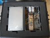
So, these were all the thoughts running around in my head while the project was underway, but the amplifiers have been returned now so it's time to clean things up. Always nice to be done, but hate to see them go. Speaking of returning them, one indication as to how fanatical a client is about their equipment shows in the detail as to how they were shipped, or want them shipped. This fellow pulled out all the stops, and had a specially designed Pelican case made to ship the amplifiers in. This thing is too cool, with form fitted heavy duty foam on the inside that form a cocoon for the amplifiers to sit in. As to the durability and security it provides, I had images of the old luggage commercial with the gorilla having at it with the Samsonite suitcase going through my mind.

And with that, it closes the book on this Fairchild project. A few final pics taken right before they left are included.

Dave

SAM_3031.JPG

SAM_3032.JPG

SAM_3033.JPG
 
Back
Top Bottom