CIRCUIT ANALYSIS FINALE
1.
NFB Loop: Since this thread is about the Fairchild 275, I thought it best to include performance information on the loop of the original design offered as well, since some of those units are surely out there. At the very least, it would satisfy my own curiosity. Therefore, I went ahead and disconnect the networks installed, and tacked in the original NFB/HF stability networks, configured for the max damping (damping off) configuration. If there was any doubt before, there is none now. The changes were clearly made to address significant stability issues, in at least the max damping configuration:
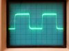
Refer to Post 25 and the first two pic presented: The magazine scope shot of the unit producing a 40 watt 6 kHz square wave, and this unit here with the updated NFB design producing a 40 watt 6 kHz square wave, both with the damping set for maximum. Now look at the following pic: Look familiar? It too is the unit producing a 40 watt 6 kHz square wave, but with the original FB and HF stability networks installed:
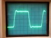
The third pic in Post 25 was of a 10 kHz square wave, and for comparison, a 10 kHz waveform made under the same conditions is presented here:
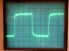
The overcompensation employed is more evident at this frequency, but still, the improvement in transient response is quite evident over that of the updated design. However, as I originally mused in my remarks when the original pics were presented in Post 25, in my experience, square wave presentations of this type and frequency from a feedback amplifier invariably imply HF stability problems, and boy oh boy, the original design had it in spades:
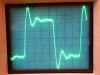
Below is a pic of a 10 kHz square wave, with no load other than a .005 uF cap connected to the 16Ω output:

Here the unit is on the verge of breaking into full blown oscillation. Look closely and you'll see the faint scatter image behind the main image indicating that condition. With just .0075 uF capacitance in place, the unit becomes a 70 watt radio station, disrupting every radio in the lab. So both of the Fairchild NFB and HF stabilization networks had notable issues -- the original design producing good transient performance but poor stability (which btw operates with 16 db of NFB), and the updated version producing good stability but poor transient performance -- and both while set to the max damping position. That means that as originally suspected, simply wiring either network in the damping "off" configuration results in notably less than optimum performance capability.
SIDEBAR: This is hardly a slam against Fairchild. The mid 50's was a time of great change in the High Fidelity industry. The power wars were beginning, stereo was on the horizon, new and higher performing tubes were becoming available, and the very definition of what a stable NFB Amplifier looked like had yet to be developed. Up until that time manufacturer's wrestled with amplifier stability, and not just a few of them. Nor was it limited to the also ran names, either. Fisher, Heath, Eico, Acro, Scott and others all had their headaches with amplifier stability issues, resulting in numerous versions (or revisions) or even new model numbers to distance some units from their previous history. Often -- and I do mean often -- in trying to deal with stability issues, the manufacturer would make revisions that took certain aspects of performance from one end of the spectrum completely to the other, causing just as many, but now different performance problems in the process. Fisher did this with their 50A design series, Heath with their early Williamson series, and others did so with some of their models as well. Some may remember threads I've done on these and other amplifiers that were dealing with
exactly the same thing, as a proper balance of performance attributes had not been struck at the time. So the performance issues identified are hardly unique to the Fairchild 275, but the result of changing understandings that were happening overnight. As with so many of the affected models however, by the time even the earliest understandings of what good NFB stability represented came to be, previous models were either by then out of production, or new designs were replacing the old, so that what was, was simply, what was.
CONTINUING: With this understanding of both Fairchild networks then, development work on the new NFB loop and HF stability networks is now finished. In every case where this type of modification work has been done, the performance improvements are audible and notable: marginally stable NFB amplifiers tend to sound harsh in the upper registers, while overly compensated amplifiers ten to sound dull or lacking in detail. When a proper emphasis/compromise is placed on all the relevant issues that make up total amplifier performance, then performance is optimized, and the listening experience enhanced.
Every effort was made to use as many elements from both Fairchild versions as possible to minimize the design changes, and simplify the modifications required. The results are quite significant:
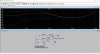
1. Frequency response is now ruler flat from 20Hz to 20 kHz (+/- 0.1 db), with a smooth roll off above and below this band, being down 0.5 DB at 40 kHz, and 6 db at 2 Hz (LF unchanged from original design).
2. Square waveform (10 kHz) as previously presented, with 3 µs rise time, less than 5% overshoot, excellent damping, and a very flat top -- all indicative of a highly stable NFB amplifier in the supersonic range.
3. Fast settling with no bounce under pulsed conditions.
4. Absolute stability into any conceivable loading condition (short, open, capacitance only).
5. The level control does not cause any significant change to a 10 kHz square wave at any midpoint setting.
Details of the new NFB loop and HF Stability networks will be given at the end of the circuit analysis section.
OUTPUT TUBE TESTS
EL34 and KT88 tubes were tried in the output stage. EL34s produced a slight power loss (~ 8 watts), but was most notably more challenged at 20 kHz. This no doubt is due to the winding capacitance within the large output transformer, that the higher current capabilities of the 6550 and KT88 tubes are better able to deal with. Somewhat surprisingly, the KT88 and 6550 tubes performed virtually identically, so these tubes can be used interchangeably. For those wishing to use EL34 tubes in 275 amplifiers, they can do so if an 18K resistor is connected in parallel with R19. Otherwise, there is not enough bias control range on the low end of the control to accommodate EL34 tubes.
Just a few mop up details to present next time, but with analysis of nearly all the critical circuit elements finished now, a restoration plan that optimizes the amplifiers can now be made, and restoration work begin in earnest.
Dave