

You are using an out of date browser. It may not display this or other websites correctly.
You should upgrade or use an alternative browser.
You should upgrade or use an alternative browser.
rca 19K low volume
- Thread starter steve1a
- Start date
Register to hide this ad
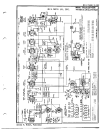
The first 6sf5 usually for low audio. On a rare occasion the 6h6 and the 6sk7 IF. When I do a full restoration, I re-tube it all and perform an alignment of the IF. Tinny sometimes is caused by the drift in the 2nd IF capacitors, but a 1/4 turn of the slug in both directions of the 2nd if transformer is going to tell you that is the case. Use a plastic rf alignment tool if you do that. Since I don't have a sound sample its hard to tell you if the IF transformer is out of alignment.i have replaced the filter caps on my RCA 19K and both 6F6G tubes test very weak .would this be why volume in tinney and low orderd 2 replacements, that would be a good place to start, any help ,
Attachments
Last edited:
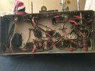
Thanks just orederd a full set of nos tubes ,looks like someone changed alot of the caps but did,t change the filter caps,replaced crispy wires ,hopefully i get it up and running,just orderd a diddle stick, the way i got it,
The first 6sf5 usually for low audio. On a rare occasion the 6h6 and the 6sk7 IF. When I do a full restoration, I re-tube it all and perform an alignment of the IF. Tinny sometimes is caused by the drift in the 2nd IF capacitors, but a 1/4 turn of the slug in both directions of the 2nd if transformer is going to tell you that is the case. Use a plastic rf alignment tool if you do that. Since I don't have a sound sample its hard to tell you if the IF transformer is out of alignment.
Attachments
Last edited:
Menco mica caps?Thanks just orederd a full set of nos tubes ,looks like someone changed alot of the caps but did,t change the filter caps,replaced crispy wires ,hopefully i get it up and running,just orderd a diddle stick, the way i got it,
Might have to go through and make sure they are the correct values. Originally it was mostly wax paper types. But I wouldn't want to use one in the outputs from plate to cathode and that value was .003 uF on those outputs. Polypropylene or Mylar Film there if they didn't want the wax paper. Also recheck the can capacitor connections. Something doesn't look correct as I remember that was a very crowded area.
thanks for helping, i,m still learning ,be a good thing to get rid of the mica caps, and replace with Polypropylene, they put caps on the tone conrol think there wrong, not sure .the trans former has black paint on it not sure what was done there, put a new cord in, just put out a bundle on tubes hope this dosnt turn into a train wreck,Menco mica caps?
Might have to go through and make sure they are the correct values. Originally it was mostly wax paper types. But I wouldn't want to use one in the outputs from plate to cathode and that value was .003 uF on those outputs. Polypropylene or Mylar Film there if they didn't want the wax paper. Also recheck the can capacitor connections. Something doesn't look correct as I remember that was a very crowded area.
Attachments
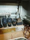

Well it could have been some one selling as an antique and put period capacitors as a way to try to keep the antique value even though its not original. So it would be something I would go through and work it all out. The Mica caps are actually very good for some things and would work well everywhere but the inrush suppressor circuit of the output stage where self healing types are used normally. That is used for the inrush current coming from tuning in the radio station which is only in radio audio. What I do if you don't own one is get a LCR meter or a DMM that has the capacitor function so you can look at the values of them. You will have to at least disconnect one of the leads of the capacitor so you can test it out of the circuit. Btw this one does not have a high voltage bleed resistance in circuit so you need to discharge it safely with a clip lead to ground and touch one of the power supply caps with the other lead. Then check DC voltage to make sure you discharged it. On these while I work on them I tack in a 470K resistor from the power supply cap to ground and allow 5-10 minutes to go by after powering it off and check the DC so I don't have to arc discharge it with a clip lead. Power cord looks ok in the picture but change it out if it has cracks. I like to use a polarized cord and make sure the smaller blade goes through the switch. Even though this isn't necessary it brings it up to current code where the hot line voltage is on the switch side. There are not many coupling and decoupling capacitors so its not a big deal. The two areas I would change out if the values for the other ones are correct would be the plate to cathode capacitors in the output stage (0.0033uf) https://www.amplifiedparts.com/products/capacitor-630v-metal-film-tubular ($0.65 ea) and a new power supply and cathode bypass cap https://www.amplifiedparts.com/products/can-capacitor-ce-manufacturing-450v-10101010-f (for the cathode bypass cap in the output stage, tie two sections together ) and a mounting clamp https://www.amplifiedparts.com/products/capacitor-clamp-1375-diameter-vertical-mounting or mounting plate https://www.amplifiedparts.com/products/mounting-plate-metal-1375-can-capacitor or two mounting clips if you don't want to drill a hole for the mounting plate or chassis https://www.amplifiedparts.com/products/spring-clip-1375-diameter-can-capacitors since there really is no intrinsic value to stuffing the old capacitor can and it brings the main part that wears out the most into the standard design everyone has settled on for the past 50 years.thanks for helping, i,m still learning ,be a good thing to get rid of the mica caps, and replace with Polypropylene, they put caps on the tone conrol think there wrong, not sure .the trans former has black paint on it not sure what was done there, put a new cord in, just put out a bundle on tubes hope this dosnt turn into a train wreck,
The capacitors that drift and make it go out of radio alignment are inside the IF transformer housing and its better to leave them alone and trim the transformer slug if it needs it.
If I was fully restoring it I would get some cloth wire and replace the heat shrink wires and not be messy with routing it even though originally they were not that neat with wires on this build.
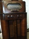
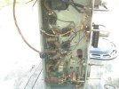
Here is one that is original
Attachments
Last edited:
Thank you for the help, hope i can save it, still learning ,no just enough to get inWell it could have been some one selling as an antique and put period capacitors as a way to try to keep the antique value even though its not original. So it would be something I would go through and work it all out. The Mica caps are actually very good for some things and would work well everywhere but the inrush suppressor circuit of the output stage where self healing types are used normally. That is used for the inrush current coming from tuning in the radio station which is only in radio audio. What I do if you don't own one is get a LCR meter or a DMM that has the capacitor function so you can look at the values of them. You will have to at least disconnect one of the leads of the capacitor so you can test it out of the circuit. Btw this one does not have a high voltage bleed resistance in circuit so you need to discharge it safely with a clip lead to ground and touch one of the power supply caps with the other lead. Then check DC voltage to make sure you discharged it. On these while I work on them I tack in a 470K resistor from the power supply cap to ground and allow 5-10 minutes to go by after powering it off and check the DC so I don't have to arc discharge it with a clip lead. Power cord looks ok in the picture but change it out if it has cracks. I like to use a polarized cord and make sure the smaller blade goes through the switch. Even though this isn't necessary it brings it up to current code where the hot line voltage is on the switch side. There are not many coupling and decoupling capacitors so its not a big deal. The two areas I would change out if the values for the other ones are correct would be the plate to cathode capacitors in the output stage (0.033 https://www.amplifiedparts.com/products/capacitor-630v-metal-film-tubular033uf) ($0.65 ea) and a new power supply and cathode bypass cap https://www.amplifiedparts.com/products/caacturing-450v-10101010-f n-capacitor-ce-manuf(for the cathode bypass cap in the output stage, tie two sections together ) and a mounting clamp https://www.amplifiedparts.com/products/capacitor-clamp-1375-diameter-vertical-mounting or mounting plate https://www.amplifiedparts.com/products/mounting-plate-metal-1375-can-capacitor or two mounting clips if you don't want to drill a hole for the mounting plate or chassis https://www.amplifiedparts.com/products/spring-clip-1375-diameter-can-capacitors since there really is no intrinsic value to stuffing the old capacitor can and it brings the main part that wears out the most into the standard design everyone has settled on for the past 50 years.
The capacitors that drift and make it go out of radio alignment are inside the IF transformer housing and its better to leave them alone and trim the transformer slug if it needs it.
If I was fully restoring it I would get some cloth wire and replace the heat shrink wires and not be messy with routing it even though originally they were not that neat with wires on this build.
Here is one that is original
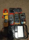
Thank you for the help , Hope i can save it i no just enough to get into trouble, this is what i have picked up for meters so far just have to learn how to use them. just orderd this will it be enough and the right gage,Wire, 20 AWG Solid Core, Lacquered Cloth Cover, 600V, Black, Length: 25 feetWell it could have been some one selling as an antique and put period capacitors as a way to try to keep the antique value even though its not original. So it would be something I would go through and work it all out. The Mica caps are actually very good for some things and would work well everywhere but the inrush suppressor circuit of the output stage where self healing types are used normally. That is used for the inrush current coming from tuning in the radio station which is only in radio audio. What I do if you don't own one is get a LCR meter or a DMM that has the capacitor function so you can look at the values of them. You will have to at least disconnect one of the leads of the capacitor so you can test it out of the circuit. Btw this one does not have a high voltage bleed resistance in circuit so you need to discharge it safely with a clip lead to ground and touch one of the power supply caps with the other lead. Then check DC voltage to make sure you discharged it. On these while I work on them I tack in a 470K resistor from the power supply cap to ground and allow 5-10 minutes to go by after powering it off and check the DC so I don't have to arc discharge it with a clip lead. Power cord looks ok in the picture but change it out if it has cracks. I like to use a polarized cord and make sure the smaller blade goes through the switch. Even though this isn't necessary it brings it up to current code where the hot line voltage is on the switch side. There are not many coupling and decoupling capacitors so its not a big deal. The two areas I would change out if the values for the other ones are correct would be the plate to cathode capacitors in the output stage (0.0033uf) https://www.amplifiedparts.com/products/capacitor-630v-metal-film-tubular ($0.65 ea) and a new power supply and cathode bypass cap https://www.amplifiedparts.com/products/can-capacitor-ce-manufacturing-450v-10101010-f (for the cathode bypass cap in the output stage, tie two sections together ) and a mounting clamp https://www.amplifiedparts.com/products/capacitor-clamp-1375-diameter-vertical-mounting or mounting plate https://www.amplifiedparts.com/products/mounting-plate-metal-1375-can-capacitor or two mounting clips if you don't want to drill a hole for the mounting plate or chassis https://www.amplifiedparts.com/products/spring-clip-1375-diameter-can-capacitors since there really is no intrinsic value to stuffing the old capacitor can and it brings the main part that wears out the most into the standard design everyone has settled on for the past 50 years.
The capacitors that drift and make it go out of radio alignment are inside the IF transformer housing and its better to leave them alone and trim the transformer slug if it needs it.
If I was fully restoring it I would get some cloth wire and replace the heat shrink wires and not be messy with routing it even though originally they were not that neat with wires on this build.
Here is one that is original
Attachments
Last edited:
Its a simple radio to get started with and learn. I would first just look at the mica capacitor values first for the correct value and change the ones I recommended. There is a guide for the molded mica caps to see their value: https://www.amplifiedparts.com/tech-articles/capacitance-value-molded-mica-calculator But its a good thing to measure them too. This is the wire I recommend: https://www.amplifiedparts.com/products/wire-20-awg-stranded-core-lacquered-cloth-cover-600v Make sure its 600V wire since the maximum voltage the radio produces is ~350V. The trick with cloth bound wire is to cut the length plus 3 inches, push back the cloth jacket 3 inches to expose the wire, cut the excess cloth jacket, strip the inner wire about 1 1/2 inches, push the jacket back to cover the inner insulator on the stripped end, then strip the other end. Wrap the wire around the solder eyelet twice. I use a pair of small needle nose pliers to do this. Then solder, then cut the excess lead.Thank you for the help, hope i can save it, still learning ,no just enough to get in
Thank you for the help , Hope i can save it i no just enough to get into trouble, this is what i have picked up for meters so far just have to learn how to use them. just orderd this will it be enough and the right gage,Wire, 20 AWG Solid Core, Lacquered Cloth Cover, 600V, Black, Length: 25 feet
I recommend a 35W soldering iron with chisel tip like this one: Weller SL335 Solder Iron 33W with PL113 Tip for Heater 1237S | SL335 - Power Soldering Accessories - Amazon.com and a good solder pump like this one to remove the solder: https://a.co/d/07lTDUoJ. Remember to only use these tools with old stuff lead solder. Also use lead solder: https://a.co/d/0dmrWE4H. Never mix lead free with lead solder on any electronics as well as use dedicated tools for lead and lead free solder work. Also remember to clean the excess flux after soldering with alcohol and a cue tip since the rosin flux is conductive.
Last edited:

Well its not original build. I posted a picture of one in #7. The only place mica caps don't work well is in the snubbing circuit in the audio output. Because they would short out over time.There is rarely a need to change mica caps, if these are original I wouldn't swap them unless you know they are bad and can do an alignment on the radio. Mica parts are usually in tuned circuits and even small changes in value will throw it off.
thanks for the help, I have a weller 8200 iron and a pencil iron and a xpower smd rework station differnt sizes of solder ,de soldering wick, just bought that desoldering pen,2 tube tester a jackson 649-s and a mercury 1100B,seting up a dim blub ,till i find a good used varaic, one of meters is suppose to have a singal genaretor on it, have yet to figure that out ,thanks for all your help i do appreciate it.Its a simple radio to get started with and learn. I would first just look at the mica capacitor values first for the correct value and change the ones I recommended. There is a guide for the molded mica caps to see their value: https://www.amplifiedparts.com/tech-articles/capacitance-value-molded-mica-calculator But its a good thing to measure them too. This is the wire I recommend: https://www.amplifiedparts.com/products/wire-20-awg-stranded-core-lacquered-cloth-cover-600v Make sure its 600V wire since the maximum voltage the radio produces is ~350V. The trick with cloth bound wire is to cut the length plus 3 inches, push back the cloth jacket 3 inches to expose the wire, cut the excess cloth jacket, strip the inner wire about 1 1/2 inches, push the jacket back to cover the inner insulator on the stripped end, then strip the other end. Wrap the wire around the solder eyelet twice. I use a pair of small needle nose pliers to do this. Then solder, then cut the excess lead.
I recommend a 35W soldering iron with chisel tip like this one: Weller SL335 Solder Iron 33W with PL113 Tip for Heater 1237S | SL335 - Power Soldering Accessories - Amazon.com and a good solder pump like this one to remove the solder: https://a.co/d/07lTDUoJ. Remember to only use these tools with old stuff lead solder. Also use lead solder: https://a.co/d/0dmrWE4H. Never mix lead free with lead solder on any electronics as well as use dedicated tools for lead and lead free solder work. Also remember to clean the excess flux after soldering with alcohol and a cue tip since the rosin flux is conductive.
Last edited:
.003 uF
i have replaced all the tubes with good ones, still very low volume .havent checked the mica caps yet , not great with diagrams in that area where the mica are , are the caps .005mfd , just want recap but the old papper one,s are gone , so i not shure what was there , on the tone switch you can click 7 spots the frist3 work after that goes dead , sprayed with dexoit fader no change,looks like they recap that tone switch not shure they have the right caps on that. just orderd resistor kits from 1/4 watt up to 3 watt, don,t leave it pluged in for a minute to see if tubes helped ,no change , i put in the bottom a new set of nichicon filter caps,still low volume, chance it could be the transformer on the speaker gone bad, not shure where this is on chassie cathode capacitors in the output stage (0.0033uf) still pretty new at this, have alot to learn,thanks for the help, I have a weller 8200 iron and a pencil iron and a xpower smd rework station differnt sizes of solder ,de soldering wick, just bought that desoldering pen,2 tube tester a jackson 649-s and a mercury 1100B,seting up a dim blub ,till i find a good used varaic, one of meters is suppose to have a singal genaretor on it, have yet to figure that out ,thanks for all your help i do appreciate it.
Last edited:
one half of the tone control switch is the radio and the other half is the rca plug in the back.i have replaced all the tubes with good ones, still very low volume .havent checked the mica caps yet , not great with diagrams in that area where the mica are , are the caps .005mfd , just want recap but the old papper one,s are gone , so i not shure what was there , on the tone switch you can click 7 spots the frist3 work after that goes dead , sprayed with dexoit fader no change,looks like they recap that tone switch not shure they have the right caps on that. just orderd resistor kits from 1/4 watt up to 3 watt, don,t leave it pluged in for a minute to see if tubes helped ,no change , i put in the bottom a new set of nichicon filter caps,still low volume, chance it could be the transformer on the speaker gone bad, not shure where this is on chassie cathode capacitors in the output stage (0.0033uf) still pretty new at this, have alot to learn,
What you can do first is get the audio stage sorted out first and then work on the radio part afterwards.
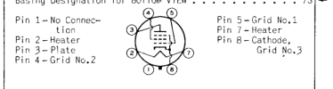
First thing you want to do is get print outs of the tube data sheets' pin out illustrations so you can look at the pins from the solder side because the schematic doesn't number the pins.
Here is the service manual that has all the info.
I would get something that plays music through an rca jack so you can put some audio on it. I use an old phone with a rca adapter cord.
The output transformer is mounted on the speaker. Sometimes they do fail. But it most likely not be a bad transformer because you had sound running through it. If the speaker is bad you can just use an 8 ohm speaker after remounting the output transformer.
Attachments
Last edited:
Thank you, i counted [5] .005 mfd caps around the 6f6gtubes good place to start replaceing caps, with a 472J @ 630V, i hooked like a echo dot to the back rca jack same low volume as the radio,think i should replace the[ 2] 470k resistors comeing from the plate of 6SF5,S think there 1/4 watt ,can you verify that ,don,t trust my skills,one half of the tone control switch is the radio and the other half is the rca plug in the back.
What you can do first is get the audio stage sorted out first and then work on the radio part afterwards.
First thing you want to do is get print outs of the tube data sheets' pin out illustrations so you can look at the pins from the solder side because the schematic doesn't number the pins.
Here is the service manual that has all the info.
I would get something that plays music through an rca jack so you can put some audio on it. I use an old phone with a rca adapter cord.
The output transformer is mounted on the speaker. Sometimes they do fail. But it most likely not be a bad transformer because you had sound running through it. If the speaker is bad you can just use an 8 ohm speaker after remounting the output transformer.
Last edited:
almost like the garage i take my car to, keep changing parts till they get it,maybe before throwing a lot of parts at it with no diag, get some voltage readings first.

Last edited:
replaced 5 of the domino ,s and up running strong,almost like the garage i take my car to, keep changing parts till they get it,
the 470k resistors are the grid to ground bias resistors. The plate only has the wire from the output connected to it and a snubbing cap 0.0033-0.005 uF which I would lift those capacitors out of circuit temporarily especially if the voltages were not correct at the plates (~240VDC). Take a look at the tube data sheet since you need the illustration of the tube socket from the soldering side. The 470 ohm resistor and the 20 uF capacitor in the cathode circuit is where the gain will go awry, and very rarely the 470K resistors are going to fail (because less than 1/8W of current goes through them). But if you replace the 470K 1/4 w resistor they should theoretically be the same resistance measured with a meter.Thank you, i counted [5] .005 mfd caps around the 6f6gtubes good place to start replaceing caps, with a 472J @ 630V, i hooked like a echo dot to the back rca jack same low volume as the radio,think i should replace the[ 2] 470k resistors comeing from the plate of 6SF5,S think there 1/4 watt ,can you verify that ,don,t trust my skills,
I gave him a digital copy of the service manual I have on file in post #14. So eventually he will get it. Still strange why someone would stick those vintage mica caps in other than it might trick someone into thinking it was original and increase a non existent antique value when the cabinet is the antique value of it.maybe before throwing a lot of parts at it with no diag, get some voltage readings first.
Similar threads
- Replies
- 4
- Views
- 452


