

You are using an out of date browser. It may not display this or other websites correctly.
You should upgrade or use an alternative browser.
You should upgrade or use an alternative browser.
RCA 4VF534 Console restoration
- Thread starter DavidBalding
- Start date

DavidBalding
Member
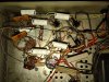
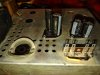
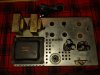
Worked on the amp side of the house today. Replaced all the film caps and the cans. Also installed a fuse and a new cord. With the film caps, since the modern ones do not have the outer film end marked, I used an oscilloscope to find the end as to minimize any noise once it's back in action. (Yes in fact one of the coupling capacitors was a dead short. So for those that are tempted to just plug up an old tube radio without checking, it might look fine on the outside, but if it's original definitely replace with new ones. All caps for the amp was about 67 dollars including shipping from Mouser.)
Attachments
DavidBalding
Member
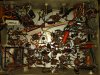
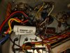
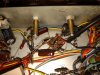
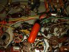
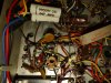
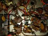
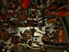
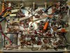
Removed the RC-1211A tuner to start work on replacing components on it. There is a total of 85 capacitors. My question for the group is do I replace every one or the film and electrolytic capacitors? There are dipped capacitors everywhere too. What is the life span on those typically?
Attachments
-
 IMG_20220127_170221589.jpg184.8 KB · Views: 21
 -
 IMG_20220127_170230212.jpg102.2 KB · Views: 21
 -
 IMG_20220127_170235773.jpg137.3 KB · Views: 20
 -
 IMG_20220127_170242508.jpg138.7 KB · Views: 19
 -
 IMG_20220127_170247607.jpg135.2 KB · Views: 19
 -
 IMG_20220127_170252705.jpg154.4 KB · Views: 18
 -
 IMG_20220127_170259080.jpg141.1 KB · Views: 21

If this were mine, I'd change the can cap, the black sleeved electrolyic up near the front, and possibly those two white caps near the selector. The white caps would depend if they are paper or not. There are some ceramic tube caps with epoxy ends that are actually a film cap, and those usually hold up OK unless mechanically disturbed. The leads break internally and they go open circuit sometimes. The ones I'm thinking of are typically branded Ceracap.
Otherwise I wouldn't change any of the rest of it unless it was giving me trouble. Looks like mostly epoxy dipped film and ceramic types, both of which are reliable. The ceramics are probably tuner related and screwing with most of that will force a re-alignment.
Otherwise I wouldn't change any of the rest of it unless it was giving me trouble. Looks like mostly epoxy dipped film and ceramic types, both of which are reliable. The ceramics are probably tuner related and screwing with most of that will force a re-alignment.


DavidBalding
Member
I thought about it but since I couldn't find exact values for the caps I figured I'd throw the cans away. The boards worked really well.I see you used the Adapt-a-cap boards. They are handy but don't preserve the look if that is important. I have tbought of gluing the original can over the top. Would almost look original.
John
DavidBalding
Member
Since the radio section works I'll leave those alone. I did order a signal generator today so that I can do an alignment once it's all together. Thanks for the help.If this were mine, I'd change the can cap, the black sleeved electrolyic up near the front, and possibly those two white caps near the selector. The white caps would depend if they are paper or not. There are some ceramic tube caps with epoxy ends that are actually a film cap, and those usually hold up OK unless mechanically disturbed. The leads break internally and they go open circuit sometimes. The ones I'm thinking of are typically branded Ceracap.
Otherwise I wouldn't change any of the rest of it unless it was giving me trouble. Looks like mostly epoxy dipped film and ceramic types, both of which are reliable. The ceramics are probably tuner related and screwing with most of that will force a re-alignment.
DavidBalding
Member
Thank you. I didn't realize the dipped ones were film.I see about five caps to change - the dipped ones are film, the ceramic ones seldom go bad. And any in the IF or RF circuits will affect alignment.
DavidBalding
Member
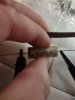
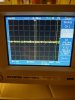
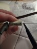
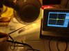
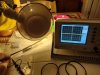
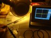
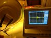
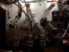
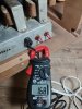
I didn't get to show this while recapping the amp, however I thought I'd share with doing the tuner side. Capacitors used to have the foil end marked so that they could be installed to minimize noise. Granted the polarity for these doesn't matter circuit wise but it does make a difference in the noise induced into the amplifier circuit. Using an oscilloscope, one can determine which end is the foil end. By switching the leads around and holding a 60 hz line cord to induce noise, one way will have less noise than the other. As you can see one foil end matched the labeling reading left to right. The other one didn't. I marked the end with a sharpie where the ground lead from the probe attached to with the least amount of noise showing up on the scope.
Attachments
-
 IMG_20220204_111439417.jpg48 KB · Views: 15
 -
 IMG_20220204_111354444_HDR.jpg113.4 KB · Views: 15
 -
 IMG_20220204_111350936.jpg55.6 KB · Views: 14
 -
 IMG_20220204_111048559_HDR.jpg96.4 KB · Views: 15
 -
 IMG_20220204_111031802_HDR.jpg100.6 KB · Views: 17
 -
 IMG_20220204_111028180.jpg93.7 KB · Views: 16
 -
 IMG_20220204_110535917_HDR.jpg92.5 KB · Views: 17
DavidBalding
Member

DavidBalding
Member
DavidBalding
Member
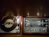
Thank you! The turntable needs a little work. Oiling and a new cartridge but it plays. It sounds beautiful. I had a Brahms record playing during dinner that was my late grandfather's and the wife asked if we were hearing a record. She couldn't believe how clear and warm the sound was. This is the way records were supposed to be played. Nothing beats an analog sound.Nice looking turntable. Great restore. Hope you really enjoy it.
John
The FM radio works 10 times better as before the frequency would shift and was in the static. I may in the near future align the AM side as it's weak but for now I've been waiting for years to hear records and want to enjoy that side of it for now. Thanks again for all your help and to the others who have provided resources and tips to bring this back to life as it was when it rolled off the line.
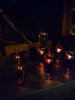
Are those RCA solid getters? I have a set of those, similar tilted getter flash. Good sounding tubes, unfortunately mine are tired and give me somewhat less than full output but they still work fine. I just have to live with 9.5 watts instead of 12.
honestly there isn't anything worth listening to on AM in most markets anyway. I like antique radios, but I've sort of fizzled on collecting them simply because they just aren't much fun to use unless I create my own source of music for them.
honestly there isn't anything worth listening to on AM in most markets anyway. I like antique radios, but I've sort of fizzled on collecting them simply because they just aren't much fun to use unless I create my own source of music for them.
DavidBalding
Member
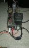
Yep and all the tubes are original. Everyone has a date stamp of 63. I was a bit worried that the ones that had red plated might have gone weak but it will crank up loud. Normal volume for me is 2 on the dial. Any higher and the walls start to rattle.Are those RCA solid getters? I have a set of those, similar tilted getter flash. Good sounding tubes, unfortunately mine are tired and give me somewhat less than full output but they still work fine. I just have to live with 9.5 watts instead of 12.
honestly there isn't anything worth listening to on AM in most markets anyway. I like antique radios, but I've sort of fizzled on collecting them simply because they just aren't much fun to use unless I create my own source of music for them.
Last edited:

I always replace all caps on the amp section of these old timers...anything electrolytic goes bye bye. I leave the can caps in place and wire new caps underneath. the resistors- carbon comp- usually drift out of spec. the diodes are replaced with new ones. love the way my combo sounds with yamaha ns 1000's...have stayed up to the wee hours listening.... yeah! had to gut one console (a long time ago)as I had no way of getting it home in a car. a lady appreciated the gift of the cabinet, though.
Attachments
DavidBalding
Member
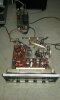
Yes I did! We use the console everyday to play music.Did you finish the restoration.i just picked up the same exact unit