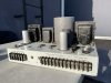
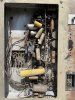
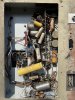
Been wanting a pair of RCA PA/theater monoblocks for a while, but never pulled the trigger -- until now. Bought a pair of these for probably more than they're worth. The seller states they're from the collection of an ex-RCA engineer, which I'd normally be skeptical of, but could be true given their obscurity.
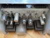
As some of you know, RCA made a number of high-power commercial monoblock amplifiers during the 1940s-1960s. It seems the most common was the MI-4288 which, based on the specs and catalogs I've seen, was aimed more at the PA market. It uses parallel push-pull 6L6s to reach the desired power level. The MI-9377A is another p-p-p 6L6 amp, but includes regulated screens. These also pop up frequently, but tend to fetch a good premium over the MI-4288, which can be had pretty cheaply. Some of RCA's big amps relied on more exotic (for audio, at least) tubes. Examples include the massive MI-12188, with a quad of 807s, and the MI-12182A, which uses a pair of 6146 transmitting tubes. MI-12182As also tend to be pretty cheap and are listed fairly often.
When I first saw these MI-112182s listed on the auction site, I assumed the seller added an extra 1 by mistake. However, upon closer inspection, I noticed the amps actually have MI-112182 silkscreened onto the chassis. At first glance, they look like MI-12182s except with a different (circular potted UTC) OPT and with 6550s instead of 6146s. Obviously this would indicate they were made, or converted, after '64. I cannot find any mentions of the MI-112182 on the internet or in any digitized RCA catalogs. The closest is a thread on the antique radio forum which mentions that MI-12182s were field converted to run 6550s due to issues with the 6146s. Apparently the OC3s were also replaced with OD3s.
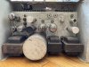
But I have my doubts these were field converted, mostly because "MI-112182" and "6550" are silkscreened. I doubt anyone doing a field modification would bother with that. Perhaps more likely that RCA produced a few of these near the end of the tube era using MI-12182 chassis. All the iron except the OPTs looks identical to the MI-12182, as does the chassis layout. Also, the cutout for the OPT looks like it was made after the chassis was fabricated. Moreover, these even have "OC3" erroneously silkscreened onto them (the tubes included are in fact OD3s).
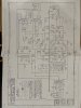
Anyways, here are some more pictures (and included schematic, which I'm not sure actually matches this amp). Curious if anyone has knowledge of these, theories, catalogs that mention them, etc. I'm curious to see how they measure once restored. Still not sure whether I want to mod them or leave the circuitry original.

As some of you know, RCA made a number of high-power commercial monoblock amplifiers during the 1940s-1960s. It seems the most common was the MI-4288 which, based on the specs and catalogs I've seen, was aimed more at the PA market. It uses parallel push-pull 6L6s to reach the desired power level. The MI-9377A is another p-p-p 6L6 amp, but includes regulated screens. These also pop up frequently, but tend to fetch a good premium over the MI-4288, which can be had pretty cheaply. Some of RCA's big amps relied on more exotic (for audio, at least) tubes. Examples include the massive MI-12188, with a quad of 807s, and the MI-12182A, which uses a pair of 6146 transmitting tubes. MI-12182As also tend to be pretty cheap and are listed fairly often.
When I first saw these MI-112182s listed on the auction site, I assumed the seller added an extra 1 by mistake. However, upon closer inspection, I noticed the amps actually have MI-112182 silkscreened onto the chassis. At first glance, they look like MI-12182s except with a different (circular potted UTC) OPT and with 6550s instead of 6146s. Obviously this would indicate they were made, or converted, after '64. I cannot find any mentions of the MI-112182 on the internet or in any digitized RCA catalogs. The closest is a thread on the antique radio forum which mentions that MI-12182s were field converted to run 6550s due to issues with the 6146s. Apparently the OC3s were also replaced with OD3s.
But I have my doubts these were field converted, mostly because "MI-112182" and "6550" are silkscreened. I doubt anyone doing a field modification would bother with that. Perhaps more likely that RCA produced a few of these near the end of the tube era using MI-12182 chassis. All the iron except the OPTs looks identical to the MI-12182, as does the chassis layout. Also, the cutout for the OPT looks like it was made after the chassis was fabricated. Moreover, these even have "OC3" erroneously silkscreened onto them (the tubes included are in fact OD3s).
Anyways, here are some more pictures (and included schematic, which I'm not sure actually matches this amp). Curious if anyone has knowledge of these, theories, catalogs that mention them, etc. I'm curious to see how they measure once restored. Still not sure whether I want to mod them or leave the circuitry original.