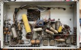
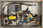
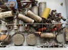
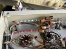
Been working on one of these for a while and finally got it sorted. Gonna run tests tomorrow. As you can see in the before pictures, tons of connections were badly spliced with thin, loosely fitting plastic, and I had to redo all of those.
I also re-configured the mains wiring, which was questionable (they put the fuse on neutral and the switch on hot...). Replaced the main B+ filter cap with a big KEMET DC link capacitor using a PCB I designed. The B+ supply is 600 volts, and I'd rather avoid using series electrolytics. The other huge axial film cap is output decoupling for the gas regulated screen supply -- I actually bought it on accident years ago and have been looking to use it in something.
I left in all the original signal path resistors, which is perhaps a controversial choice. However, this amp isn't hifi -- it doesn't have gnfb, and I have determined the output transformer is a UTC CVP-3, which is a universal PA transformer. I'd rather keep these amps as historical pieces sounding as close to original as possible, which includes the carbon comp resistors. I did measure every single one of them, and they are all within spec, so I got lucky in that respect. If they cause too much noise, I can always replace them later.
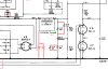
A few other major changes include removing the selenium rectifier (of course) and changing the 1/4 bias test jack configuration. They are shorting jacks and were originally configured to measure current directly -- when the plug is inserted, the shorting connection is broken and you measure the current with an ammeter. Of course, this means when there is no jack inserted the output tube current flows through the shorting connection, which I don't really trust. So I changed them to shunts, with hand-selected 10 ohm carbon comp resistors in parallel with the shorting connections. Break it and you measure voltage across the resistor. This way nothing should really happen if the shorting connection goes spotty, as there will still be a low impedance path for current flow.
You might notice the 100 ohm resistor hanging loose at the left hand side. That was part of the resistor cap combination in parallel with the choke (discussed earlier in the thread). I want to run tests with and without it to determine whether it's really necessary, as there's not really a great way to mount the capacitor.