• The move to the new server is done. There are some software and database maintenance updates in process. This has us passing the hat around to help out. We appreciate any donations. Seriously, even a dollar helps. The payment page may be found here - https://www.audiokarma.org/support.html

Realistic 210 reborn (AKA Acrosound UL120)

Brice

AK Subscriber
Subscriber
Hi guys,

I wanted to share the work I've done on a true classic amplifier, the Realistic 210,
also known as the Acrosound UL120, just rebranded by RadioShack.

As far as I know, Acrosound did sell Radioshack UL120 amplifiers just before they tragically
disappeared in 1959.

Radioshack just did a paint job and sold them as kits.

This amp is pretty much the stereo version of the famous Acrosound ULII, but with some
improvements such as solid state rectification, more PS filtration, and a bias meter switch.

IMHO this is one of the best amplifiers of that era.

I bought that amp a couple of years ago but did not do anything with it until now.
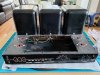
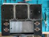
IMG_20211104_161250.jpg


The story was this amp was brought to a tech for a checkup and bias pots upgrade.
It came back to the owner without a PCB, and a bag of parts...
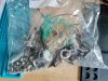
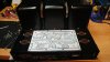
IMG_20211104_161404.jpg
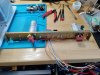
Someone added a plate instead of the PCB for a point to point
replacement but it was not completed.

A quick check confirmed that the transformers were all good, so I did not go further.

I took it out of its box a few months ago for restoration.

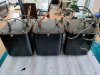
I first removed the transformers carefully and sent them for a professional paint job.
IMG_20211104_164416.jpg

IMG_20211104_171615.jpg
(On a side note, I have used a desoldering Hakko FR301 gun and it made the job so easy
and simple. Also you barely heat the wires compared to other methods so it really does not damage them.)

The transformers came back as beautiful as an automotive paint job can do. I always wrap them with
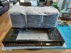
kitchen Glad cling wrap but that's not enough to prevent scratch accidents.
I add on top a Glad Press'N Seal thicker film to prevent unexpected tools damage.
IMG_20211226_134053.jpg

Next the new PCB...
 
Register to hide this ad
The PCB:

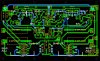
I made a PCB as close as possible as the original layout from a picture of a real board. Thanks to X3workshop for helping in scaling the picture correctly.
I placed the component first, and made a rough routing.
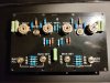
Acrosound-UL120-V1.0.JPG


Then place them correctly and route all by hand on 2 layers. I was extra careful to separate the AC heater trace with the audio path.
Also all the traces are a minimum of 2mm space from each other. It seems a lot but I had a bad experience with 1 mm only and trace leakage.
Acrosound-UL120-V1-1.JPG

I printed it on paper to make sure the dimensions were correct.


20180928_222813.jpg

I proofread it again before sending my gerber files to a printing company.
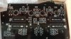
The result is this:
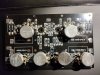
20181011_151351.jpg

IMG_20211108_180916.jpg

IMG_20211108_180926.jpg

Next the HV PS...
 
HV power supply:

I used PSU Designer II to improve the PS.
UL120-Upgraded.jpg

I planned to use an Authenticap KTL25 (80/40/30/20 @ 550V) and a KTL41 (200/50 @ 550V) as they fit perfectly into the chassis.
After various tries, the best combination was to use 80+40uF off the bridge, then the choke, then 250uF from the KTL41 for B+,
then 30uF for B+1 then 20uF for B+2.

IMG_20211226_134941.jpg

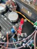
I also added a dual fuse holder to fuse the CT of each OT.
I had to adjust 1 resistor from the schematic (R5 47K) to have the B+1 correct (27K). Now the driver voltages are as the schematic.
IMG_20211226_134959.jpg

And I added a big thermistor 120R 4A to slow the startup. The startup is indeed slow and I lose 3 VAC across the thermistor, which is OK as I get over 121VAC now at my place.

Next the Bias meter...
 
Bias meter:

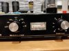
As to be expected, the original bias meter was not operating reliably.
Here is the original
Panel_ul120_1.jpg

Panel_ul120_2.jpg


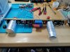
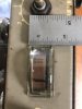
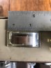
So I found a replacement one on ebay and added a trimmer for calibration. The red zone now starts at 40 mA.

IMG_20210911_192206.jpg

IMG_20210911_192221.jpg


Installing it to the chassis wasn't easy as it is bigger than the original.
I had to make a template and cut an aluminum sheet, to hold the meter in place. It worked nicely and looks quite nice IMO.
IMG_20220116_165741.jpg

IMG_20220116_173346.jpg

The downside is that the internal pilot light did not fit under the meter anymore.
So I bought a LED pcb which replaced the vintage pilot light holder. This is too bad as I like that original lighting.
IMG_20220108_124829.jpg

Next some chassis work...
 
Chassis work:

I changed the power switch and added a snubber cap, removed the damping circuitry, and used the damping switch for the pilot light.
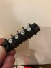
I bought speaker terminals from dynaparts, but wasn't happy with it, it was too fragile.
I found this one, a direct replacement of the vintage one and very high quality. I like them.
Ref: https://www.digikey.com/product-detail/en/curtis-industries/GFTX-4/364-1158-ND/2659885
IMG_6596.jpg

IMG_20220120_192427.jpg


The chassis was in good shape, and I cleaned it and applied marine wax everywhere.
I replaced the damping pot as a volume pot with a cheap stepped attenuator. Works.

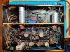
I populated the board, used NOS WW pots, and rebuilt the whole thing.

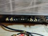
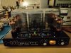
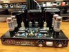
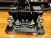
Here are some pics of the finished amplifier:

IMG_20220120_184449.jpg


IMG_20220116_175032.jpg

IMG_20220116_180912.jpg

IMG_20220126_180558.jpg

IMG_20220126_180631.jpg

IMG_20220126_180838.jpg

Next some numbers...
 
Some numbers:

The amp consumes 140 watts idle @ 36 mA power tubes.

It pushes a healthy 60 watts RMS @ 1% THD, then clips nicely and evenly above that.
This is with BOTH channels active at the same time.

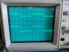
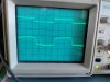
Square response is excellent.

1K
UL120-1K.jpg

10K
UL120-10K.jpg

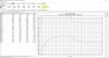
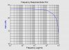
And here is the frequency response plot.
UL120.jpg

This amplifier is very musical, fast and detailed like all Acrosound amplifiers.
I really like it and I am happy to have restored it as close as possible to the original.

I hope you guys liked reading this.

Cheers,
Brice.
 
Last edited:
Great Job Brice
You are the Acro Whisperer
No doubt it will have better SQ
Than a built Citation 2
What are you using for cupeling caps?
 
Wow wow wow. One for this being a Radio Shack amp, one for the incredible job and one for the great and informative post. Amazing!
 
Incredible work and attention to detail! It is a nice looking amp for sure. It looks like their is some serious 500 vdc+ on the EL34's. Do you have a schematic you can attach? What are the specs of the OPTs?
 
The schematic should be real close to the Acrosound Stereo 120. The output transformers are Acrosound TO-600s
Which are not only Ultralinear transformers but they have a separate secondary winding which is tightly coupled to both the primary and secondary windings and which provides global feedback to the balanced driver stage.
Its brilliant and unique and holy mackerel does it work. Brice is the expert he knows these amps probably better than anyone.
Good stuff Brice you did it again.
You could make any amplifier beautiful, but it helps when you start with the very best transformers and circuit.
Wow.
 
Thanks guys for your comments.
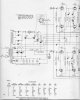
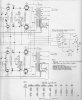
Here is the schematic. It has errors in the driver voltages, but the rest is 100% accurate.
 

Attachments

  • Acrosound 120 Schematic #1.JPG
    Acrosound 120 Schematic #1.JPG
    129.4 KB · Views: 56
  • Acrosound 120 Schematic #2.JPG
    Acrosound 120 Schematic #2.JPG
    140.8 KB · Views: 57
I'm confused as to how you generated the Gerbers? Using a picture of an original PCB did you lay it out in some PCB software so that could be accomplished?
 
Back
Top Bottom